Engine oil dilution improvement device

An oil and fuel technology, applied in mechanical equipment, engine components, machines/engines, etc., can solve the problems of low cost performance, high cost, low absolute fuel quantity, etc., to optimize oil dilution, reduce the degree of oil dilution, and eliminate mixing Possible Effects of Oil Pans

Inactive Publication Date: 2020-05-22
HITACHI AUTOMOTIVE SYST SUZHOU
View PDF19 Cites 3 Cited by
  • Summary
  • Abstract
  • Description
  • Claims
  • Application Information

AI Technical Summary

Problems solved by technology

However, on the one hand, this treatment scheme requires the design of a complex monitoring, control and separation system to separate the fuel from the engine oil, and its cost is relatively high; on the other hand, the absolute amount of separated fuel is not too high. Inexpensive compared to configuration costs of monitoring, control and separation systems

Method used


Image

  • Engine oil dilution improvement device
  • Engine oil dilution improvement device
  • Engine oil dilution improvement device

Examples


no. 1 example

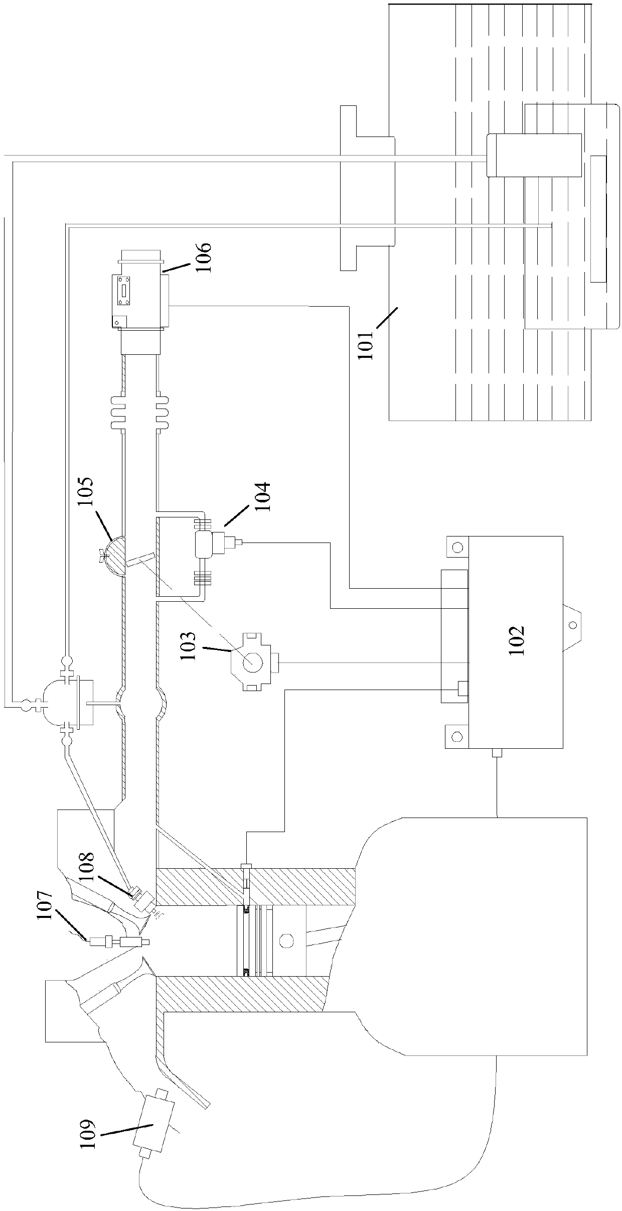
[0066] figure 1 is a schematic diagram of the overall structure of the engine control system equipped with the first embodiment of the device for improving engine oil dilution of the present invention. figure 2 is a schematic diagram of an engine cylinder equipped with a first embodiment of the device for improving oil dilution of the present invention. It can be seen that, in addition to the device for improving engine oil dilution of the present invention, the engine control system also includes a fuel pump 101, an electronic control unit 102, a throttle valve position switch 103, an idle speed actuator 104, a pressure regulator 105, an air flow rate Meter 106, spark plug 107, nozzle 108, oxygen sensor 109 and other components, the engine cylinder also includes spark plug 107 and nozzle 108 and other components. Since the structures of these components and their connections are known to those skilled in the art and are not directly related to the inventive concept of the p...

no. 2 example

[0074] Figure 4 is a schematic diagram of the general structure of the engine control system equipped with the second embodiment of the device for improving engine oil dilution of the present invention. Figure 5 is a schematic diagram of an engine cylinder equipped with a second embodiment of the device for improving oil dilution of the present invention. Figure 6 A second embodiment of the device for improving oil dilution according to the invention is shown. The above drawings and Figures 1 to 3 The content shown is basically similar.

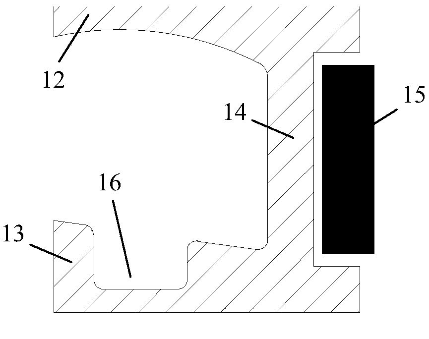
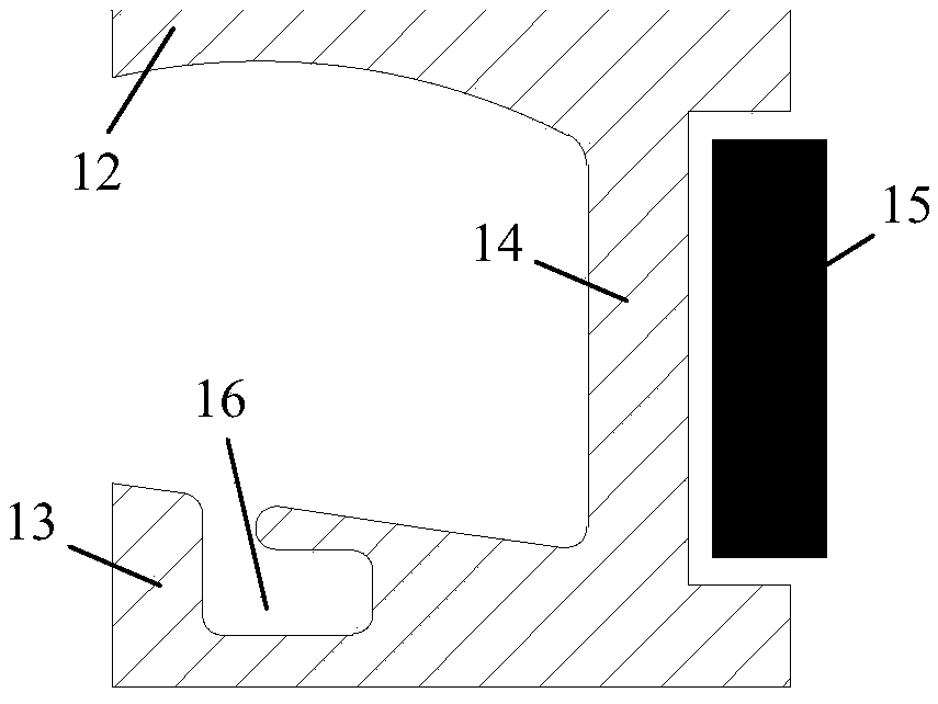
[0075] In the second embodiment of the present invention, the device for improving engine oil dilution includes an oil collector ring 10 for scraping Coanda fuel and an electronically controlled valve 11 for sucking fuel oil from the oil collector ring 10 . A total of five ring grooves are designed on the piston wall of this embodiment. Figure 6 In the middle direction from top to bottom, there are heat insulation groove 1, oil colle...

no. 3 example

[0078] Figure 7 is a schematic diagram of the overall structure of an engine control system equipped with a third embodiment of the device for improving engine oil dilution of the present invention. Figure 8 is a schematic diagram of an engine cylinder equipped with a third embodiment of the device for improving oil dilution of the present invention. Figure 9 A third embodiment of the device for improving oil dilution according to the invention is shown. The above drawings and Figures 1 to 3 The content shown is basically similar.

[0079] In the third embodiment of the present invention, the device for improving oil dilution includes an oil collector ring 10 for scraping Coanda fuel and an electronically controlled valve 11 for sucking fuel oil from the oil collector ring 10 . A total of four ring grooves are designed on the piston wall of this embodiment. Figure 9 Along the middle direction from top to bottom are the first gas ring groove 2, the second gas ring groo...


PUM


Abstract

The invention relates to an engine oil dilution improvement device. The device comprises an oil collection ring (10) used for scraping and collecting wall-attached fuel oil and an electronic control valve (11) sucking the collected fuel oil from the oil collection ring (10), wherein the oil collection ring (10) is arranged on the wall of a piston, so that the wall-attached fuel oil is collected inthe oil collection ring (10) before flowing into an oil sump, and the electronic control valve (11) sends the collected fuel oil back to a cylinder for re-combustion. Through the technical scheme ofthe engine oil dilution improvement device, the probability that the wall-attached fuel oil is mixed into the oil sump can be reduced fundamentally and even eliminated, the dilution degree of engine oil is directly and effectively reduced, and the purpose of optimizing engine oil dilution is achieved.

Description

technical field [0001] The present invention relates to a device for improving oil dilution and, more particularly, to a device for improving oil dilution by returning Coanda fuel to the cylinder and reburning it before it flows into the sump. Background technique [0002] Engine oil, that is, lubricating oil in automobile engines, has important functions such as cleaning, lubrication, sealing, and heat dissipation. Therefore, the oil in a car engine is as important as blood in a human body. When the engine is in a cold start, high speed and high load state, the fuel is prone to poor atomization. In this case, droplets of fuel adhere to the cylinder walls, then seep into the crankcase and flow into the oil sump, where they end up in the engine oil, causing it to become diluted. This phenomenon is especially evident in direct-injection engines due to insufficient atomization time and space conditions. [0003] Too much dilution of the engine oil can cause adverse consequen...

Claims


Application Information

Patent Timeline
IPC IPC(8): F02F3/00F02F5/00F02F1/18
CPCF02F1/18F02F3/00F16J9/206
Inventor 刘贤利
Owner HITACHI AUTOMOTIVE SYST SUZHOU
Why Eureka
Try Eureka