Method for regenerating a diesel particulate filter

a technology of particulate filter and regenerative method, which is applied in the direction of electrical control, process and machine control, instruments, etc., can solve the problems of affecting the efficiency of the diesel engine, not covering all possible engine working conditions with current regeneration strategies, and ineffective filters, etc., to achieve improved combustion efficiency, increase the heat release in the combustion chamber, and increase the effect of exhaust gas temperatur

Inactive Publication Date: 2011-03-17
GM GLOBAL TECH OPERATIONS LLC
View PDF9 Cites 27 Cited by
  • Summary
  • Abstract
  • Description
  • Claims
  • Application Information

AI Technical Summary

Benefits of technology

In other words, the embodiments of the invention at least differs from the current regeneration method in that the single after-injection of the prior art is split in several consecutive after-injection pulses. The interaction of such consecutive after-injection pulses causes the pulses to sustain each other in the exothermal oxidation reaction of fuel in combustion chamber. Therefore, if compared to the usual single after-injection, the consecutive after-injection pulses increase the heat release in combustion chamber, leading to better combustion efficiency with minor production of unburned hydrocarbon (HC), and to a higher exhaust gas temperature.
Moreover, the last after-injection pulse will be relatively near to the instant when the exhaust valves open the combustion chamber, so that the exhaust gas flow is generally warmer than the exhaust gas flow produced by a single after-injection. As a matter of fact, the after injection split method allows a faster and more effective DPF regeneration process, by means of which it is possible to reduce, oil dilution, and exhaust line thermal stress, as well as the risk of DPF clogging and the risk of a regeneration interruption by driver key-off.

Problems solved by technology

When the pressure drop becomes excessive, it may cause the filter body to crack, rendering the filter ineffective, or it may affect the efficiency of the diesel engine.
However, not all possible engine working condition are actually covered by current regeneration strategies.
For instance, when the engine works in the low-idle condition, current regeneration strategies get a the temperature increase which unlikely can achieve the requested target of temperature upstream DPF (due to very low temperature of the gas upstream DOC), and so the regeneration is not so efficient to completely burn the particulate matter inside the diesel particulate filter in the requested regeneration duration, especially in light application with small displacement engine and especially for under-floor configuration of DPF.
This leads to a regeneration frequency increase and / or to a longer regeneration process, which increase the risk for the regeneration process to be interrupted by driver key-off, and involve many other drawbacks too.
Most common of such drawbacks are: an increased fuel consumption, due to the high amount of post-injected fuel which is used for heating the DPF and which does not generate torque at the crankshaft (since post-injected fuel is oxidized into the DOC); an increased exhaust line thermal stress and an early component ageing (mostly on the Pre Catalyst), due to the fact that the components of the exhaust line are heated for a long time at high temperature; an increased oil dilution, due to the higher amount of post-injected fuel which tends to pass between the piston and the cylinder reaching the engine oil sump; possibility of DPF clogging if regeneration cannot be carried out at all.

Method used


Image

  • Method for regenerating a diesel particulate filter
  • Method for regenerating a diesel particulate filter
  • Method for regenerating a diesel particulate filter

Examples


Embodiment Construction

The following detailed description is merely exemplary in nature and is not intended to limit application and uses. Furthermore, there is no intention to be bound by any theory presented in the preceding background or summary or the following detailed description.

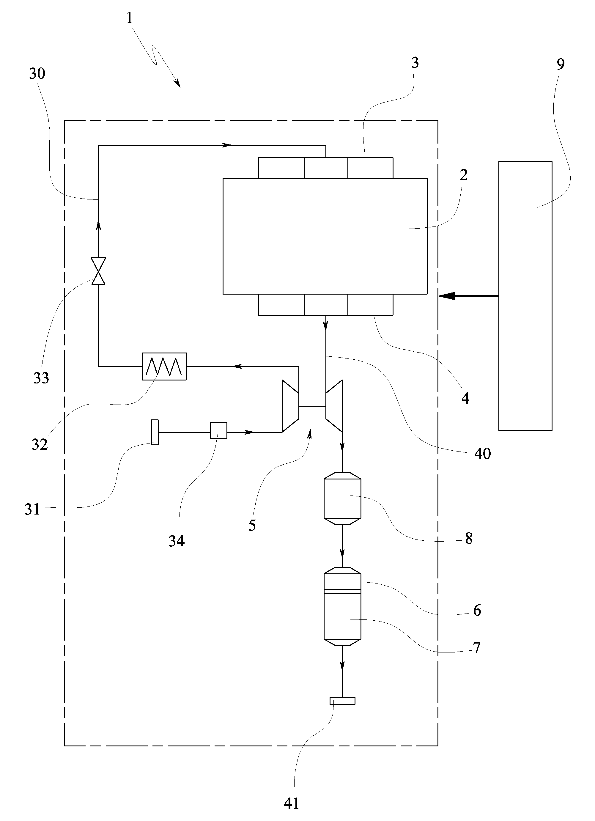
A preferred embodiment of the present invention is applied to a turbocharged diesel engine system, which is generally labeled 1 in FIG. 1. The diesel engine system 1 comprises a four-stroke engine 2 having a plurality of combustion chambers which are individually defined by a reciprocating piston inside a cylinder. Each combustion chamber is provided with: one or more intake valves, for cyclically open the corresponding chamber towards an intake manifold 3; one or more exhaust valves, for cyclically open the corresponding chamber towards an exhaust manifold 4; and electrically controllable injection means for injecting fuel into the combustion chamber. Cylinders, pistons, intake valves, exhaust valves and injection means ar...


PUM


Abstract

A method is provided for regenerating a diesel particulate filter within a diesel engine system that includes, but is not limited to at least a combustion chamber defined by a reciprocating piston inside a cylinder, at least an exhaust valve for cyclically open the combustion chamber towards an exhaust line, and the diesel particulate filter located in the exhaust line, wherein the method comprises injecting an amount of fuel into the combustion chamber by means of least two consecutive after-injection pulses (AIP1-AIP3), each of which starts (SOI) after the piston has passed the top dead center (TDC), and sufficiently near to the latter for the fuel to burn at least partially inside the combustion chamber.

Description

CROSS-REFERENCE TO RELATED APPLICATIONThis application claims priority to British Patent Application No. 0914497.3, filed Aug. 19, 2009, which is incorporated herein by reference in its entirety.TECHNICAL FIELDThe present invention relates to regeneration of a diesel particulate filter (DPF) within a diesel engine system.BACKGROUNDA diesel engine system generally comprises one or more combustion chambers which are individually defined by a reciprocating piston inside a cylinder.The cylinder is provided with one or more intake valves for cyclically opening the combustion chamber towards an intake line for receiving fresh airflow, and with one or more exhaust valves for cyclically opening the combustion chamber towards an exhaust line for discharging the exhaust gases.The cylinder is also provided with electrically controllable injection means, which are controlled by a microprocessor based controller (ECU), for injecting fuel inside the combustion chamber according to a multi-injecti...

Claims


Application Information

Patent Timeline
Patent Type & Authority Applications(United States)
IPC IPC(8): F01N3/18F02D28/00
CPCF01N3/0253F01N9/002F01N2430/06F02D41/0245F02D41/029F01N13/009F02D41/405Y02T10/44Y02T10/26Y02T10/47F02D41/08Y02T10/12Y02T10/40
Inventor CASSANI, STEFANOMERCURI, DAVIDEBARBERO, SIMONERELLECATI, PIERLUIGI
Owner GM GLOBAL TECH OPERATIONS LLC
Why Eureka
Try Eureka