Check patentability & draft patents in minutes with Patsnap Eureka AI!

Radiation flow detector array

A detector array and radiation flow technology, which is applied in the field of radiation flow detector arrays, can solve the problems of bulky detection units, low reliability, and low spatial resolution, and achieve increased detection array area, improved installation and use efficiency, and easy installation Ease of replacement

Active Publication Date: 2020-05-22
LASER FUSION RES CENT CHINA ACAD OF ENG PHYSICS
View PDF28 Cites 0 Cited by
  • Summary
  • Abstract
  • Description
  • Claims
  • Application Information

AI Technical Summary

Problems solved by technology

[0003] In laser fusion research, the spectrometer currently used is composed of single-channel radiation flow detectors. As the basic measurement unit, the radiation flow detector itself has a small volume It is relatively large, and it is necessary to establish a monochromatic energy selection optical path for each detection unit when performing energy spectrum measurement. Therefore, the entire spectrometer system is quite bulky, and there are optical path adjustment and aiming problems during the equipment installation process, resulting in the entire The system is relatively complex, which brings many difficulties to the transportation, installation, commissioning and maintenance in the application process
At the same time, due to the defect of the large volume of the detection unit itself, the spatial resolution of this type of system when measuring the energy spectrum / radiation flow is greatly restricted.
In summary, the existing energy spectrum measurement system has the disadvantages of complex structure, low reliability, large mass, and low spatial resolution

Method used


Image

  • Radiation flow detector array
  • Radiation flow detector array

Examples


Embodiment Construction

[0028] The present invention will be further explained below in conjunction with the accompanying drawings.

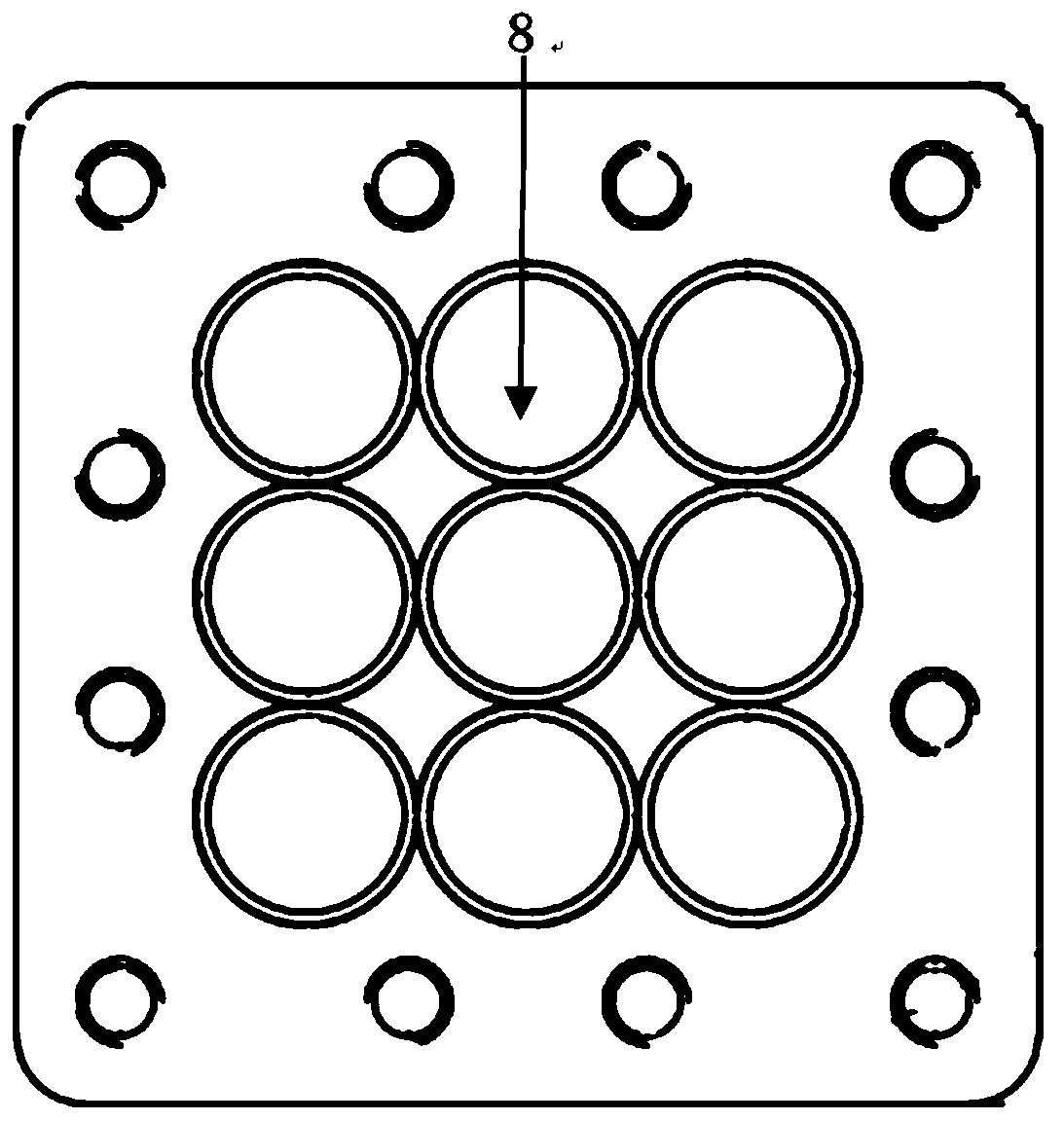
[0029] exist Figure 1~2 Among them, a radiation flow detector array includes a plurality of band-pass filter units 2 and a plurality of detection units 4 installed on an installation base, and an output interface 5 is connected to the end of each detection unit 4 .

[0030] Among them, the band-pass filter unit 2 adopts a thin-sheet energy selection structure design based on micro-channel plate technology, which can adjust the X-ray energy selection section by changing the process parameters such as the length-to-diameter ratio and bevel angle of the micro-channel plate; The unit 2 is embedded on the installation part 3 through plug-in, and the bandpass filter unit 2 can be quickly replaced according to the actual energy selection requirements; the detection unit 4 has no outer vacuum seal and shielding structure, and is integrated into a thin shell design array of c...


PUM


Abstract

The invention relates to a radiation flow detector array, which comprises an installation part, a band-pass filtering unit and a detection unit, and is characterized in that the installation part comprises a detection unit installation part, a band-pass filtering unit installation part and a connecting part between the detection unit installation part and the band-pass filtering unit installationpart. After a vacuum sealing / shielding layer of the detection unit is canceled, small-sized shell thinning is realized, and the detection unit is further integrated into a compact multi-channel detector array. In the aspect of an energy selection part, a transmission band-pass filtering technology is used, and a near-pasting plug-in mounting structure is designed, so that independent energy selection of each detection channel and miniaturization and rapid replacement of an energy selection device are realized. Meanwhile, the detection unit uses a pulse working mode to improve the stability ofthe system. The radiation flow detector array is small in size, high in stability and convenient to install and use, time / space resolution is improved, and a detection unit of the radiation flow detector array serving as a standardized array module has expansibility.

Description

technical field [0001] This patent belongs to the field of laser fusion diagnosis, and specifically relates to a radiation flow detector array. Background technique [0002] In the development of laser fusion research, with the continuous deepening of the research on the physical mechanism, the requirements for conventional X-ray radiation flow and energy spectrum measurement are getting higher and higher. [0003] In laser fusion research, the currently used spectrometer is composed of single-channel radiation flow detectors. As the basic measurement unit, the radiation flow detector itself is relatively large. When performing energy spectrum measurement, it is necessary to provide The monochromatic energy selection optical path is established separately for the unit, so the whole spectrometer system is quite bulky, and there are problems of optical path adjustment and aiming during the equipment installation process, which makes the whole system relatively complicated, whi...

Claims


Application Information

Patent Timeline
Patent Type & Authority Applications(China)
IPC IPC(8): G01T1/36G01T7/00G01V5/00
CPCG01T1/36G01T7/00G01V5/00Y02E30/10
Inventor 陈韬曹柱荣王强强邓克立邓博黎宇坤
Owner LASER FUSION RES CENT CHINA ACAD OF ENG PHYSICS
Features
  • R&D
  • Intellectual Property
  • Life Sciences
  • Materials
  • Tech Scout
  • Unparalleled Data Quality
  • Higher Quality Content
  • 60% Fewer Hallucinations
Learn More