
Laterally-placed pole

A technology of pole and roller bearings, which is applied in the field of circuit breakers, can solve the problems of circuit breaker closing sticking, affecting circuit breaker performance, breaking failure, etc., to reduce insulation interval requirements, increase connection stability, and assembly accuracy low effect

Active Publication Date: 2020-05-22
XUCHANG XJ SOFTWARE TECH
View PDF9 Cites 0 Cited by
  • Summary
  • Abstract
  • Description
  • Claims
  • Application Information

AI Technical Summary

Problems solved by technology

[0004] The solid-sealed poles of conventional vacuum circuit breakers are usually placed vertically, that is, placed vertically. The moving end and the static end of the vacuum interrupter are in the same vertical direction, generally the static end faces upwards and the moving end faces downwards; but In the prior art, there are also poles placed on the side, that is, placed horizontally, the moving end and the static end of the vacuum interrupter are in the same horizontal direction, such as (SF 6 ) The solid-sealed pole in the inflatable cabinet is placed on the side; the side-laid pole is affected by gravity, and the self-gravity of the moving contact conducting rod of the arc extinguishing chamber, the soft connection (or the moving conducting rod of the sliding connection), etc., make The moving guide rod of the arc extinguishing chamber sags, so that the guide sleeve of the arc extinguishing chamber rubs against the conductive rod of the arc extinguishing chamber, which will cause the circuit breaker to be stuck in opening and closing, affect the performance of the circuit breaker, and even cause abnormalities such as breaking failure

Method used


Image

  • Laterally-placed pole
  • Laterally-placed pole
  • Laterally-placed pole

Examples


Embodiment Construction

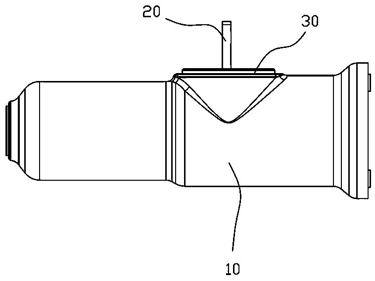
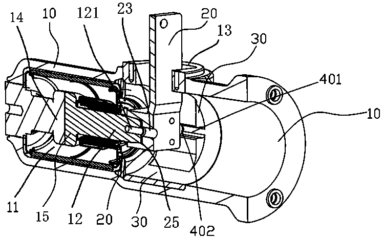
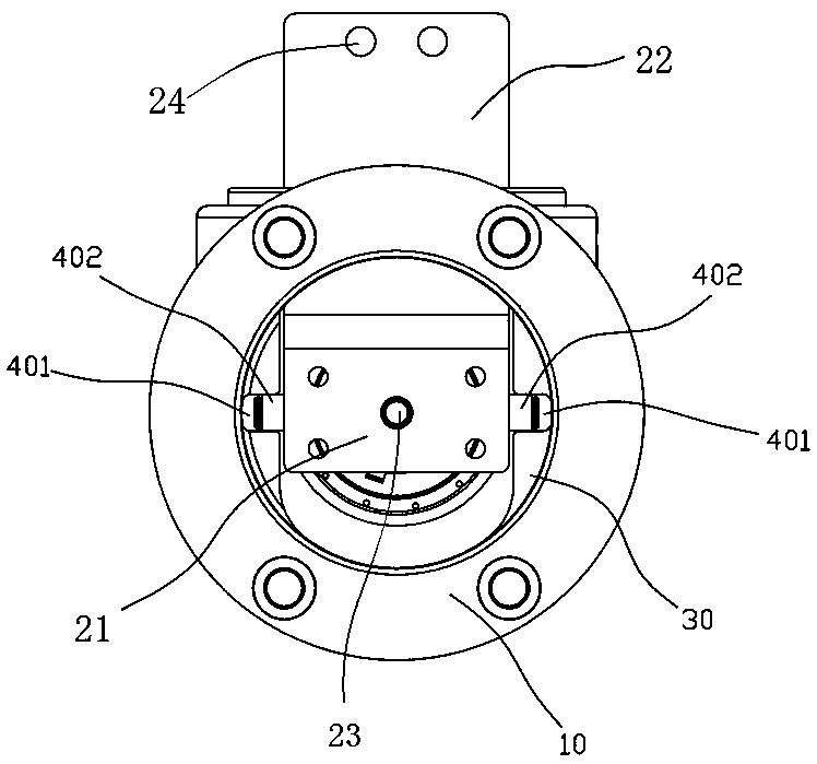
[0027] To further illustrate the various embodiments, the present invention is provided with accompanying drawings. These drawings are a part of the disclosure of the present invention, which are mainly used to illustrate the embodiments, and can be combined with related descriptions in the specification to explain the operating principles of the embodiments. With reference to these contents, those skilled in the art should understand other possible implementations and advantages of the present invention. Components in the figures are not drawn to scale, and similar component symbols are generally used to denote similar components.

[0028] The present invention will be further described in conjunction with the accompanying drawings and specific embodiments.

[0029] refer to Figure 1 to Figure 4 As shown, this embodiment provides a side discharge pole, including a pole casing, a vacuum interrupter 11 arranged in the pole casing, and an electrical connection part 20 connect...


PUM


Abstract

The invention provides a laterally-placed pole. The laterally-placed pole comprises a pole shell, a vacuum arc-extinguishing chamber arranged in the pole shell and an electric connection part connected with the moving end of the vacuum arc-extinguishing chamber, wherein the pole shell is provided with a first sliding support structure which is horizontally arranged in the side placement state of aside placement pole; the electric connection part is provided with a second sliding support structure which is in sliding fit with the first sliding support structure; the electric connection part ismatched with the first sliding support structure of the pole shell through the second sliding support structure to realize sliding and supporting in the horizontal direction, so that the electric connection part does not droop due to the influence of gravity, the electric connection part, the arc-extinguishing chamber moving contact conducting rod and other devices can be kept horizontal, the guide sleeve of the arc-extinguishing chamber and the conducting rod of the arc-extinguishing chamber are not prone to friction, and opening and closing actions are smooth and not prone to clamping stagnation.

Description

[0001] The patent application of the present invention claims the right of priority, and the prior application as the basis of the priority is a Chinese utility model patent application named "a side-mounted pole" with application number 201921233352.6. technical field [0002] The invention relates to the field of circuit breakers, in particular to a side discharge pole with smooth opening and closing action and not easy to get stuck. Background technique [0003] The embedded pole is to embed the conductive parts related to the vacuum interrupter and the circuit breaker into an easily curable solid insulating material such as epoxy resin to form a pole, so that the entire circuit breaker pole becomes an integral part. [0004] The solid-sealed poles of conventional vacuum circuit breakers are usually placed vertically, that is, placed vertically. The moving end and the static end of the vacuum interrupter are in the same vertical direction, generally the static end faces up...

Claims


Application Information

Patent Timeline
Patent Type & Authority Applications(China)
IPC IPC(8): H01H33/02H01H33/46H01H33/66H01H33/664
CPCH01H33/66H01H33/664H01H33/46H01H33/02
Inventor 吴小钊郑晓果王其中李猛白维正徐慧强李俊豪翟贺鹏汤清双张艳晓董冏
Owner XUCHANG XJ SOFTWARE TECH
Learn More