Laser diode device

A technology of laser diodes and equipment, applied in lasers, laser devices, laser parts, etc., can solve the problems of disallowing components and heat removal, and achieve the effect of improving heat removal and simplifying process control

Pending Publication Date: 2020-05-22
ROBERT BOSCH GMBH
View PDF0 Cites 0 Cited by
  • Summary
  • Abstract
  • Description
  • Claims
  • Application Information

AI Technical Summary

Problems solved by technology

However, due to the small cross section, this does n

Method used


Image

  • Laser diode device
  • Laser diode device
  • Laser diode device

Examples


Embodiment Construction

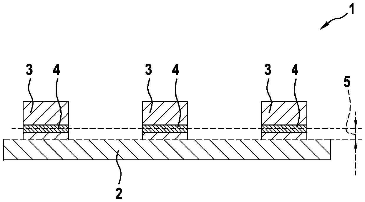
[0027] exist figure 1 A laser diode device 1 is shown in . The laser diode device 1 has a thermally conductive substrate 2 with a flat surface for dissipating heat from the surrounding environment. Substrate 2 can for example be made of AlN, Al 2 o 3 , Si or glass. A plurality of laser diodes 3 are arranged on the substrate 2 (three laser diodes 3 are shown here; however, more laser diodes 3 may also be provided, for example up to twenty). Each of the laser diodes 3 has one or more (active) epitaxial layers 4 . Epitaxial layer 4 is arranged on the side of laser diode 3 facing substrate 2 . The individual epitaxial layers 4 are placed passively above the planar substrate 2 in a plane-parallel manner with high precision at a substantially common height 5 .

[0028] The combination of the planarity of the substrate 2 and the small process fluctuations of the epitaxial layer 4 results in a very precise adjustment of the laser diode 3 perpendicular to the substrate 2 and perp...


PUM


Abstract

A laser diode device 1 includes a thermally conductive substrate 2 that has a planar surface for dissipating ambient heat, and a plurality of laser diodes 3 situated thereon, each of which includes atleast one epitaxial layer 4 that is situated on a side of the laser diode 3 facing the substrate 2. The laser diodes 2 are each electrically activated via an electrically conductive coating situatedbetween the at least one epitaxial layer 4 and the substrate 2. The substrate 2 includes a plurality of metallized cavities that accommodate the plurality of laser diodes 3 so that the plurality of laser diodes have an essentially uniform height above the substrate.

Description

technical field [0001] The invention relates to a laser diode device with a thermally conductive substrate having a flat surface for dissipating heat from the surrounding environment and a plurality of laser diodes, the laser diodes being arranged on the thermally conductive substrate on the bottom and each have at least one epitaxial layer, wherein at least one epitaxial layer is arranged on the side of the laser diode facing the substrate, wherein the electrically conductive layer arranged between the at least one epitaxial layer and the substrate respectively The laser diode is electrically controlled. Background technique [0002] Such laser diodes are known. In this case, the laser diode can have a plurality—preferably between one and five—epitaxial layers. [0003] In this context, it is also known in the prior art that in order to increase the optical emission power of a laser diode device, it is sometimes necessary to operate a plurality of semiconductor chips in p...

Claims


Application Information

Patent Timeline
IPC IPC(8): H01S5/022H01S5/024H01S5/40
CPCH01S5/02469H01S5/4025H01S5/0236H01S5/02355H01S5/0237H01S5/042H01S5/02325H01S5/0216
Inventor M·安贝格尔G·布林克斯T·措勒尔
Owner ROBERT BOSCH GMBH
Why Eureka
Try Eureka