
Heat dissipation assembly and cooking utensil with same

A technology for heat-dissipating components and cooking utensils, applied in the fields of cooking utensils and heat-dissipating groups, can solve the problems of large space occupied by insulation cotton, inconvenient installation process, affecting the service life of electrical components and electrical control components, etc. The effect of simple assembly and simplified structure

Pending Publication Date: 2020-05-26
GUANGDONG MIDEA KITCHEN APPLIANCES MFG CO LTD +1
View PDF0 Cites 3 Cited by
  • Summary
  • Abstract
  • Description
  • Claims
  • Application Information

AI Technical Summary

Problems solved by technology

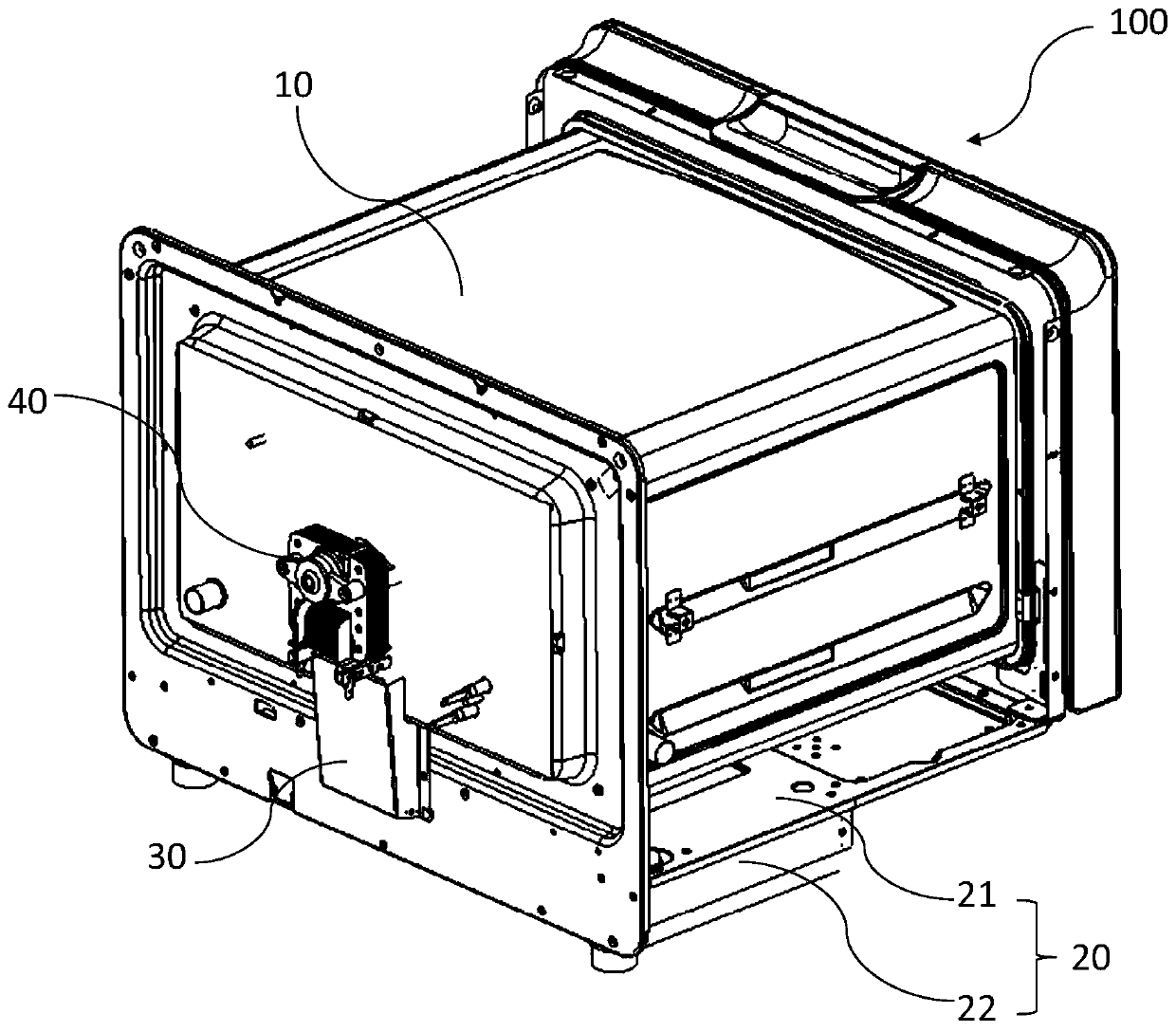
[0003] A cooking appliance (such as a steam box or a steam oven) includes electrical components, an electric control component, and a box body with a cooking cavity. Both the electrical component and the electric control component are arranged on the box body. During the food cooking process, the high temperature of the cooking cavity will be transmitted to the electrical components and the electric control components, thus affecting the service life of the electrical components and the electric control components
[0004] In the prior art, the electrical control components and electrical components are separated from the cabinet by arranging thermal insulation materials such as thermal insulation cotton on the outside of the cabinet, so as to avoid the influence of the high temperature of the cooking cavity on the electrical control components and electrical components. However, Insulation cotton takes up a lot of space, and the installation process is inconvenient

Method used


Image

  • Heat dissipation assembly and cooking utensil with same
  • Heat dissipation assembly and cooking utensil with same
  • Heat dissipation assembly and cooking utensil with same

Examples


Embodiment Construction

[0042] Exemplary embodiments of the present disclosure will be described in more detail below with reference to the accompanying drawings. Although exemplary embodiments of the present disclosure are shown in the drawings, it should be understood that the present disclosure may be embodied in various forms and should not be limited by the embodiments set forth herein. Rather, these embodiments are provided for more thorough understanding of the present disclosure and to fully convey the scope of the present disclosure to those skilled in the art.

[0043] It should be understood that the terminology used herein is for the purpose of describing particular example embodiments only and is not intended to be limiting. As used herein, the singular forms "a", "an" and "the" may also be meant to include the plural forms unless the context clearly dictates otherwise. The terms "comprising", "comprising", "containing" and "having" are inclusive and thus indicate the presence of stated...


PUM


Abstract

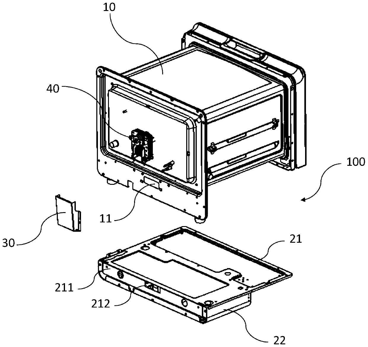
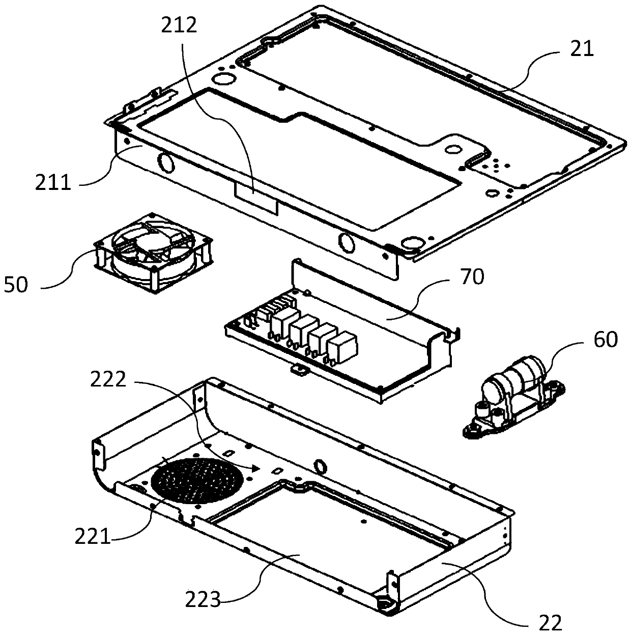
The invention discloses a heat dissipation assembly and a cooking utensil with the same. The heat dissipation assembly comprises a base, at least one air guide piece and a draught fan. The base is used for being arranged at the bottom of a box of the cooking utensil. The base is provided with a containing cavity and an air inlet hole communicated with the containing cavity. The containing cavity is used for installing an electric control assembly of the cooking utensil, the air guide piece is provided with an air guide channel, one end of the air guide channel is communicated with the containing cavity, the other end of the air guide channel is used for being communicated with an electric assembly installation area located on the outer side of the box body, and the draught fan is arrangedin the containing cavity and used for circulating external air to the containing cavity and the electric assembly installation area. When the heat dissipation assembly is used for the cooking utensil,under the action of the draught fan, external air enters the containing cavity through air inlet holes, exchanges heat with the electric control assembly, then reaches the electric assembly installation area through the air guide channel and exchanges heat with the electric assembly, multi-position cooling of the electric control assembly and the electric assembly is achieved, the structure of the heat dissipation assembly is simplified, the occupied space is small, and assembling is easy.

Description

technical field [0001] The invention relates to the technical field of cooking equipment, in particular to a heat dissipation group. The invention also relates to a cooking appliance. Background technique [0002] This section provides background information related to the present disclosure only and is not necessarily prior art. [0003] A cooking appliance (such as a steam box or a steam oven) includes electrical components, an electric control component, and a box body with a cooking cavity. Both the electrical component and the electric control component are arranged on the box body. During the food cooking process, the high temperature of the cooking cavity will be transmitted to the electrical components and the electric control components, thereby affecting the service life of the electrical components and the electric control components. [0004] In the prior art, the electrical control components and electrical components are separated from the cabinet by arrangin...

Claims


Application Information

Patent Timeline
Patent Type & Authority Applications(China)
IPC IPC(8): A47J27/04A47J36/00A47J37/06
CPCA47J27/04A47J36/00A47J37/0629A47J37/0641A47J2027/043
Inventor 胡广川邓雁青李国保周飞李星
Owner GUANGDONG MIDEA KITCHEN APPLIANCES MFG CO LTD
Learn More