
Injection mold for optical lens

A technology for injection molds and optical lenses, which is applied to optical components, household appliances, and other household appliances. It can solve problems such as thimbles easily scratching optical lenses, affecting performance, and complicated operations, and achieves stable and reliable mold closing and mold opening actions. , high processing efficiency and reliable structure

Active Publication Date: 2021-07-23
浙江烨嘉光电科技有限公司
View PDF5 Cites 0 Cited by
  • Summary
  • Abstract
  • Description
  • Claims
  • Application Information

AI Technical Summary

Problems solved by technology

[0003] In the prior art, the molds used to make optical lenses mainly include upper and lower molds with upper and lower mold cavities and ejection structures. When the molds are closed, the upper and lower molds move close together. After the mold is opened, the ejection structure is used to eject the obtained optical lens. The operation is complicated. The ejection action is completed by the ejector pin. performance, and during the ejection process, the thimble is also easy to scratch the surface of the optical lens and form defects

Method used


Image

  • Injection mold for optical lens
  • Injection mold for optical lens
  • Injection mold for optical lens

Examples


Embodiment Construction

[0018] In order to further understand the features, technical means, and specific objectives and functions achieved by the present invention, the present invention will be further described in detail below in conjunction with the accompanying drawings and specific embodiments.

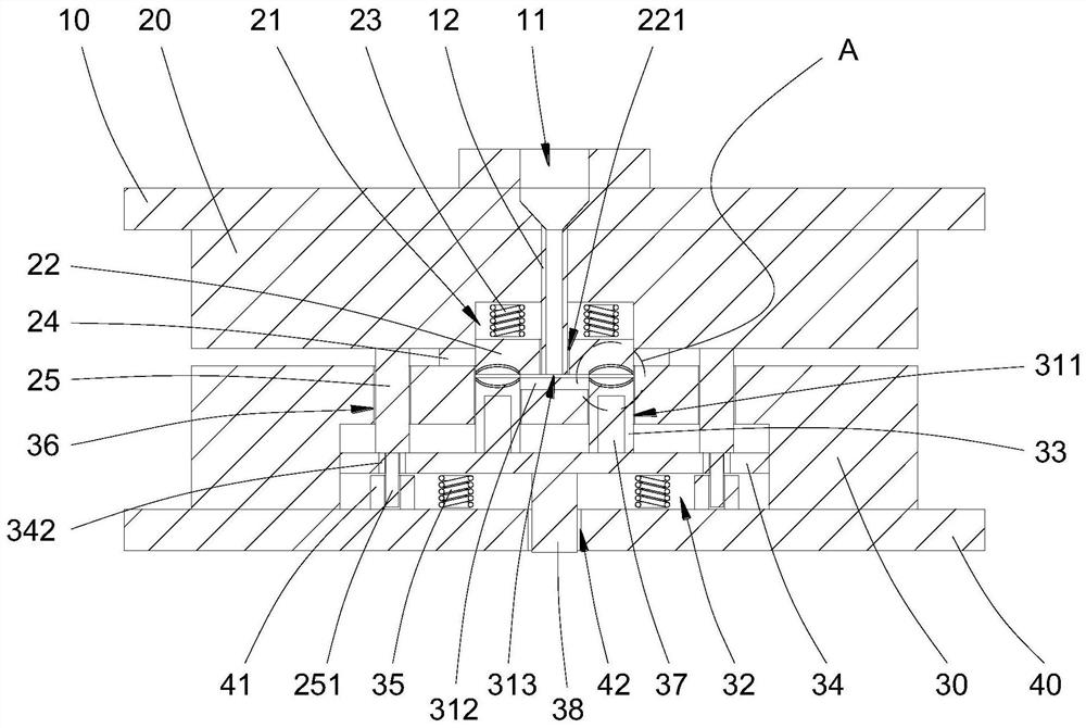
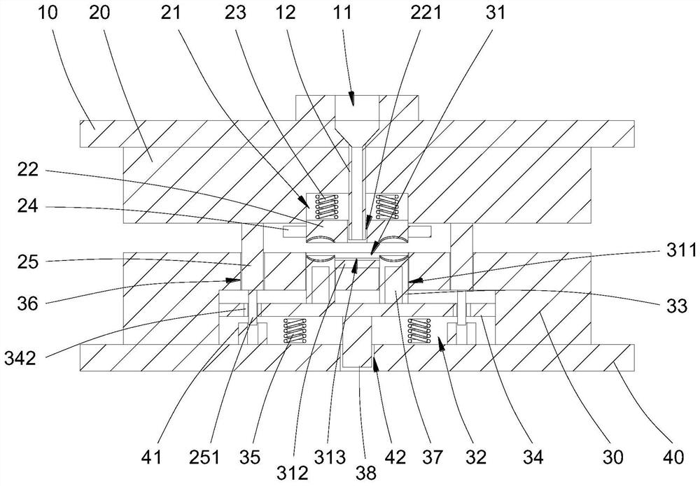
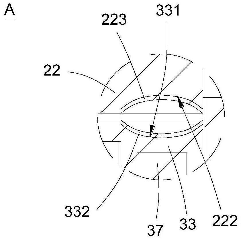
[0019] refer to Figure 1 to Figure 3 .

[0020] The embodiment of the present invention discloses an injection mold for an optical lens, comprising an upper backing plate 10, an upper mold 20, a lower mold 30 and a lower backing plate 40, the upper backing plate 10 is provided with an injection gate 11, and the injection gate 11 is connected below There is an injection plastic pipe 12 set through the upper mold 20, the injection plastic pipe 12 is fixed in the upper mold 20, the bottom of the upper mold 20 is provided with a push-pull relief groove 21, and a push plate 22 is arranged in the push-pull relief groove 21, and the push plate 22 is provided with an injection molding channel 221, and the in...


PUM


Abstract

The invention provides an injection mold for optical lenses. The bottom of the upper mold is provided with a push-pull relief groove, and a push plate is arranged in the push-pull relief groove. The bottom of the push plate is provided with an upper molding surface. The top of the push plate passes through the first The spring is connected with the push-pull relief groove, the bottom of the upper mold is fixed with a linkage column, and the bottom of the linkage column is fixed with a magnet lifting column; the lower mold is provided with a mold cavity, and the bottom of the mold cavity is connected with a mold core guide hole, and the mold core guide hole The bottom of the mold core is connected with a lifting cavity, the mold core guide hole is slidably connected with a mold core column, the top of the mold core column is provided with a lower forming surface, the bottom of the mold core column is fixed with a top plate, and a first magnetophilic metal sleeve is arranged in the top plate. The bottom of the top plate is connected with the lifting cavity through the second spring, and a linkage guide hole is also provided in the lower die. The invention can avoid burrs and gaps at the edge of the injection molding cavity, has high processing efficiency, matches the surface of the ejection structure with the surface of the optical lens, and can ensure that the surface of the produced optical lens is smooth and free of defects.

Description

technical field [0001] The invention relates to an injection mold, and specifically discloses an injection mold for an optical lens. Background technique [0002] Optical lenses refer to transparent materials with one or more curved surfaces made of optical materials such as glass or resin, and are used in optical systems and other structures. When using resin to make optical lenses, it is necessary to use a mold to achieve molding. [0003] In the prior art, the molds used to make optical lenses mainly include upper and lower molds with upper and lower mold cavities and ejection structures. When the molds are closed, the upper and lower molds move close together. After the mold is opened, the ejection structure is used to eject the obtained optical lens. The operation is complicated. The ejection action is completed by the ejector pin. performance, and during the ejection process, the thimble can easily scratch the surface of the optical lens and form defects. Contents ...

Claims


Application Information

Patent Timeline
Patent Type & Authority Patents(China)
IPC IPC(8): B29C45/26B29C45/33B29C45/40B29L11/00
CPCB29C45/0025B29C45/2602B29C45/2606B29C45/33B29C45/332B29C45/401B29C2045/0036B29C2045/4063B29L2011/0016
Inventor 南基学
Owner 浙江烨嘉光电科技有限公司
Learn More