Torsion damper and power transmission device

A technology of power transmission and torsional shock absorber, which is applied in the direction of spring/shock absorber, vibration suppression adjustment, mechanical equipment, etc., and can solve problems such as transmission belt and transmission pin slippage

Pending Publication Date: 2020-05-26
SUZHOU HUIMEI AUTOMOTIVE TECH CO LTD
View PDF1 Cites 1 Cited by
  • Summary
  • Abstract
  • Description
  • Claims
  • Application Information

AI Technical Summary

Problems solved by technology

[0004] The object of the present invention is to provide a torsional shock absorber and a power transmission device to solve the problem of slippage between the spring of th

Method used


Image

  • Torsion damper and power transmission device
  • Torsion damper and power transmission device
  • Torsion damper and power transmission device

Examples


Embodiment 1

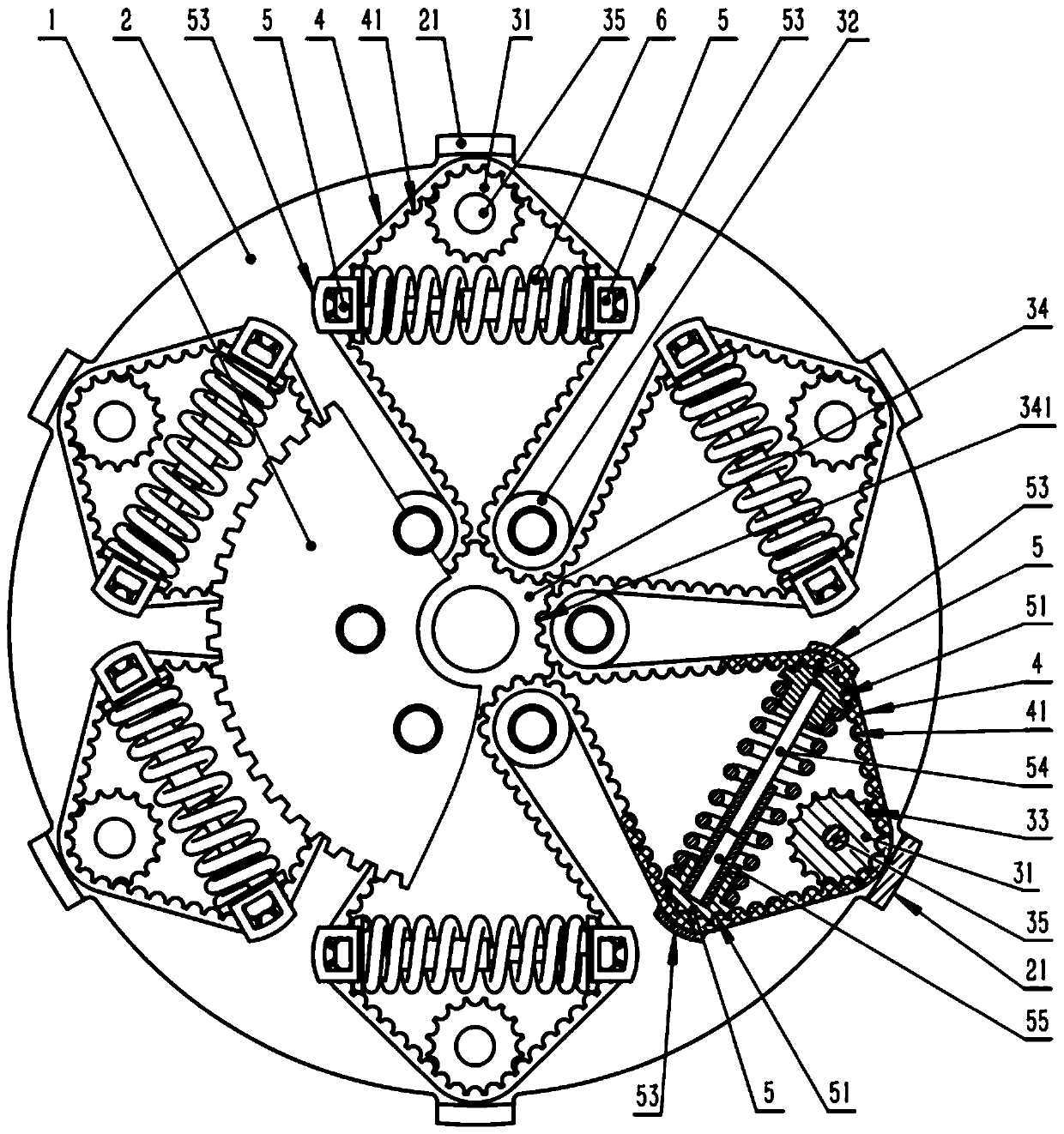
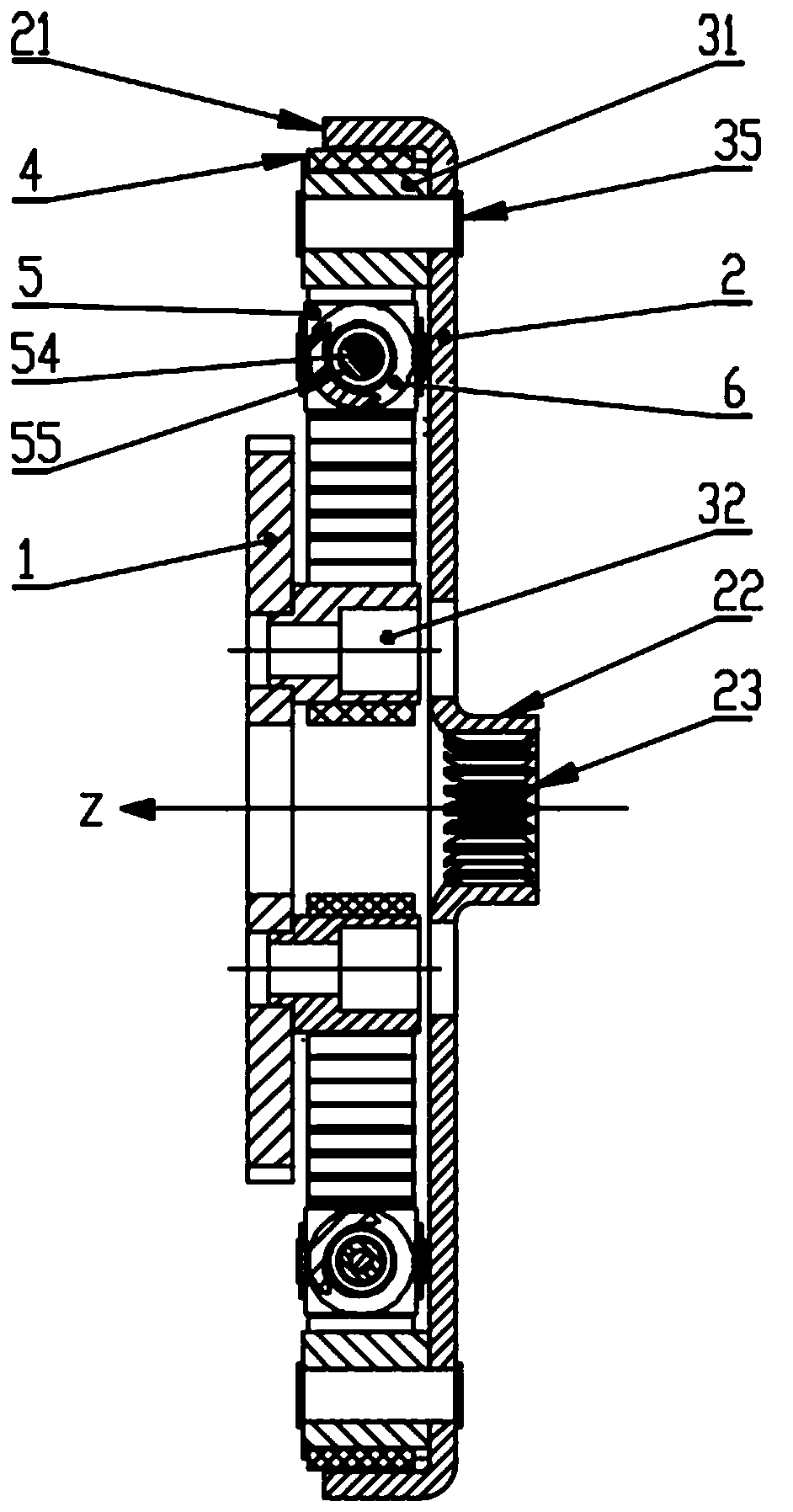
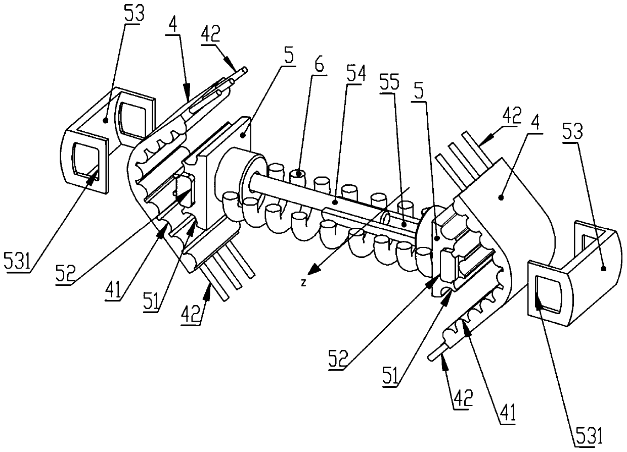
[0044] Such as Figure 1 to Figure 6 As shown, the present invention provides a torsional vibration absorber and a power transmission device, and the power transmission device includes a first flywheel 1, a second flywheel 2 and a torsional vibration damper. Wherein the first flywheel 1 and the second flywheel 2 are coaxially arranged along the Z axis, and in this embodiment, the first flywheel 1 is located above the second flywheel 2 . The torsional damper includes an outer drive pin 31, an inner drive pin 32, a drive belt 4 and a spring seat 5, the number of the outer drive pins 31 and the inner drive pins 32 are the same, and the outer drive pins 31 are arranged at the edge of the second flywheel 2 at equiangular intervals, and the inner drive pins 32 are arranged at the center of the first flywheel 1 at equal angular intervals, that is, the outer transmission pin 31 is arranged on the outer periphery of the inner transmission pin 32 . The transmission belt 4 has a closed ...

Embodiment 2

[0062] see Figure 7 , the present invention provides another kind of power transmission device, the difference from Embodiment 1 is that the outer transmission pin 31 is arranged on the first flywheel 1 as the power input end, and the inner transmission pin 32 is arranged on the second flywheel 2 as the power output end , and the center of the second flywheel 2 is provided with a stop claw 34, and the inner peripheral surface of the stop claw 34 is provided with a spline 23. At this moment, the spline 23 and the stop claw 34 are provided as an integral structure.


PUM


Abstract

The invention belongs to the technical field of engines, and discloses a torsion damper and a power transmission device. The torsion damper comprises external transmission pins, internal transmissionpins, a transmission belt and spring seats, the multiple external transmission pins are arranged on the peripheries of the internal transmission pins with the same number, the multiple internal transmission pins are arranged along the same circumference, the transmission belt is of a closed S-shaped structure and is connected with all the external transmission pins and internal transmission pins,the radial inner side of each external transmission pin is provided with the corresponding pair of spring seats, each pair of spring seats is elastically connected through an elastic piece, and the transmission belt is engaged with all the external transmission pins and all the spring seats. The power transmission device comprises a first flywheel, a second flywheel and the torsion damper. The torsion damper and the power transmission device have the beneficial effects that the torsion damper has nonlinear and progressive torsion damping rigidity, and the damping effect is good; and a plurality of contact positions of the transmission belt are engaged, thus the sliding phenomenon of engaging teeth is not prone to occurring, the structural stability of moving parts of the torsion damper isimproved, and the service life of the moving parts of the torsion damper is prolonged.

Description

technical field [0001] The invention relates to the technical field of engines, in particular to a torsional shock absorber and a power transmission device. Background technique [0002] Due to the combustion knocking of the engine, unavoidable torsional vibration is caused during the rotation of the output shaft, which is harmful to the power transmission system and also causes vibration and noise. In order to reduce the torsional vibration, it is necessary to add a set of torsional damper between the engine output shaft and the transmission input shaft. [0003] For example, the Chinese invention patent CN201910222964.3 is a dual-mass flywheel, in which the torsional damper includes a transmission belt, a transmission pin, a spring and a spring seat. When the flywheel rotates at a high speed, the spring, the spring seat and the transmission belt itself generate a huge centrifugal force. This centrifugal force will cause slippage between the spring and the transmission bel...

Claims


Application Information

Patent Timeline
IPC IPC(8): F16F15/315F16F15/131F16F15/134
CPCF16F15/131F16F15/13407F16F15/1343F16F15/315
Inventor 袁辉袁梓玉袁梓彤
Owner SUZHOU HUIMEI AUTOMOTIVE TECH CO LTD
Why Eureka
Try Eureka