Slip ring mechanism

A technology of slip rings and copper rings, applied in current collectors, electrical components, rotating current collectors, etc., can solve the problem of poor sliding contact between brush wires and slideways, weak welding between cables and brush wires, and poor power and signal transmission. Stability and other issues to achieve the effect of ensuring power and signal transmission, saving operating time, and simple operation

Active Publication Date: 2020-05-26
HANGZHOU HIKVISION DIGITAL TECH
View PDF11 Cites 10 Cited by
  • Summary
  • Abstract
  • Description
  • Claims
  • Application Information

AI Technical Summary

Problems solved by technology

In the prior art, the stator and the rotor are in sliding contact through the brush wire, the brush wire is welded to the cable, and the cable is connected to the power supply, and the residue generated by the welding of the brush wire and the cable will enter the slideway of the sliding contact, so that the brush wire and the slide The sliding contact of the slip ring is poor, or the welding between the cable and the brush wire is not firm, resulting in unstable power and signal transmission, which affects the normal use of the slip ring

Method used


Image

  • Slip ring mechanism
  • Slip ring mechanism
  • Slip ring mechanism

Examples


Embodiment Construction

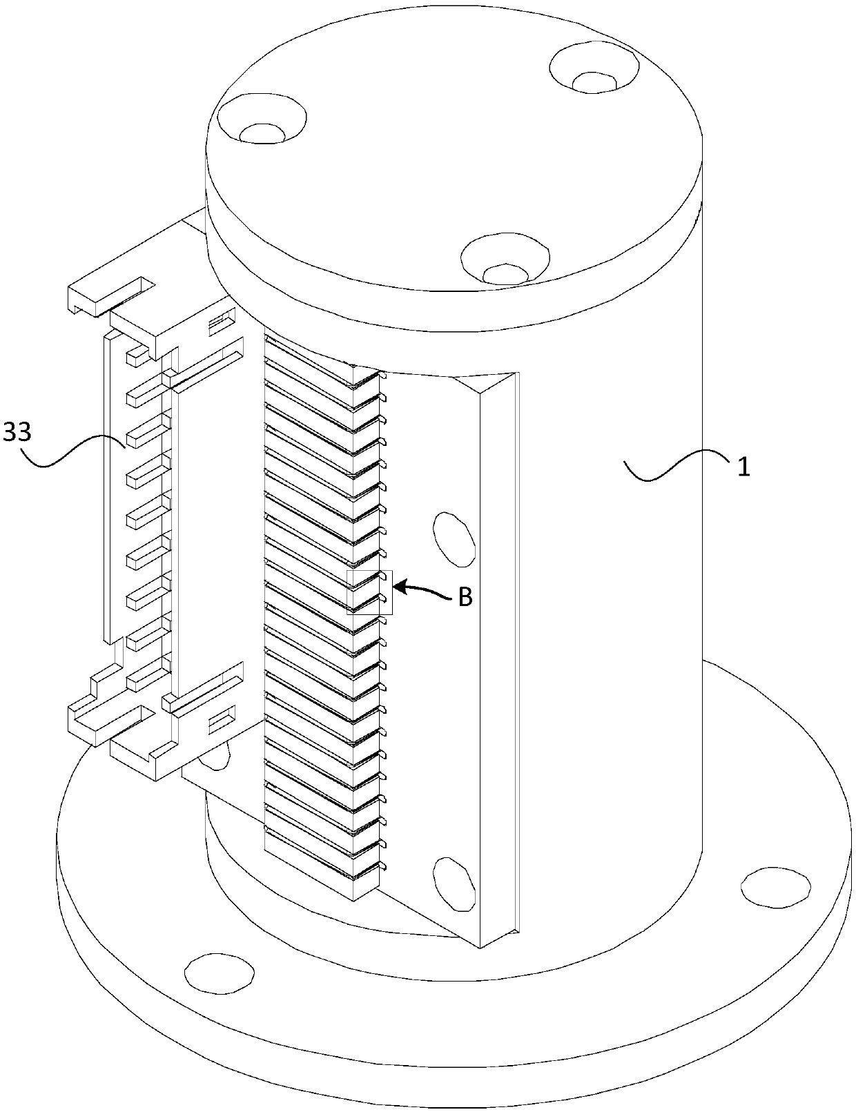
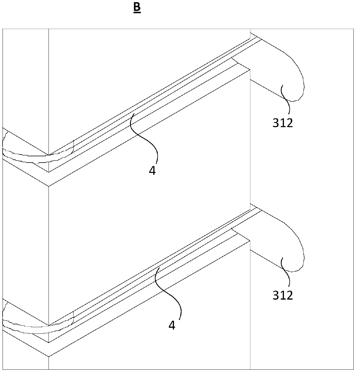
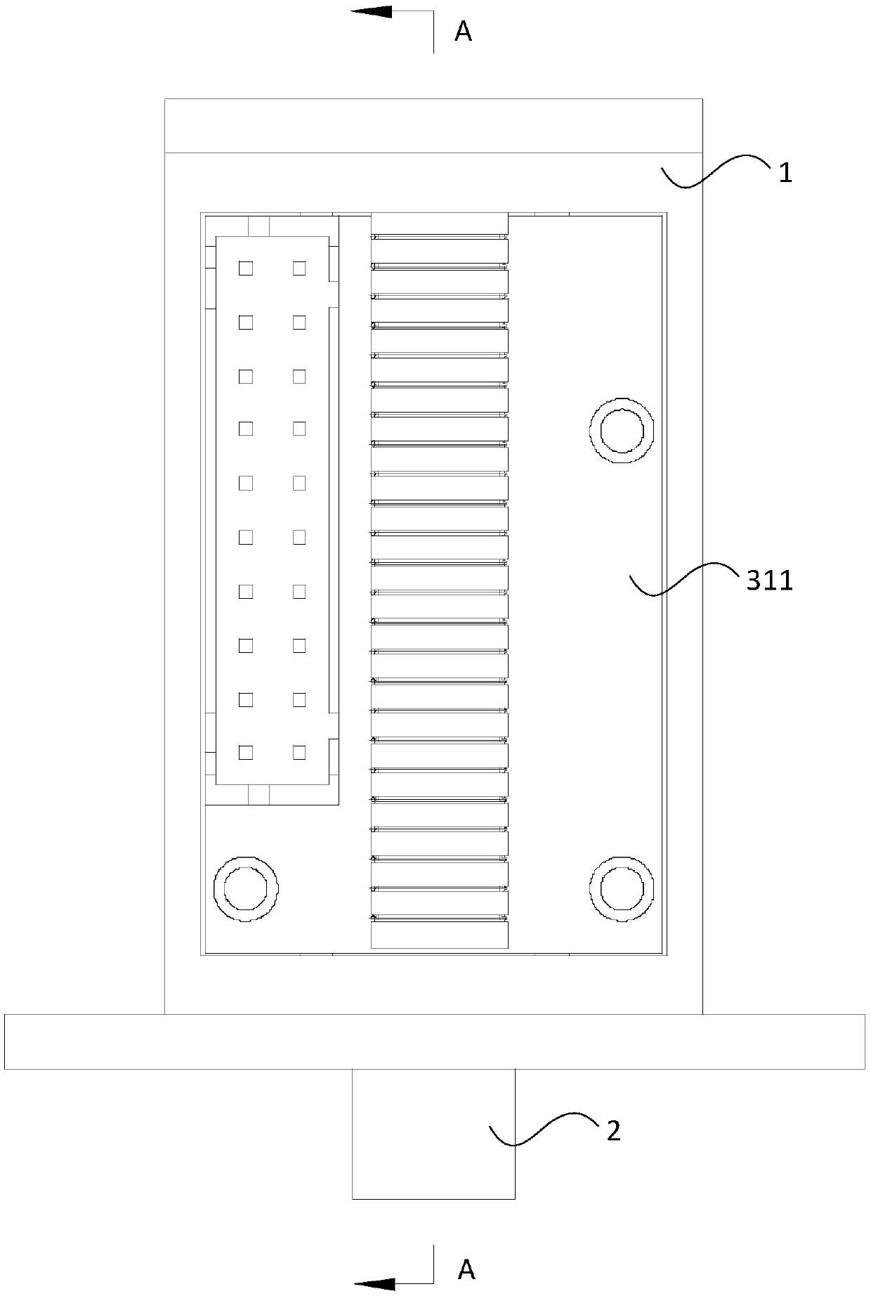
[0046] In order to have a clearer understanding of the technical features, purposes and effects of the invention, the specific implementation manners of the present invention will now be described with reference to the accompanying drawings, in which the same reference numerals represent the same parts.

[0047] In this article, "schematic" means "serving as an example, example or illustration", and any illustration or implementation described as "schematic" should not be interpreted as a more preferred or more advantageous Technical solutions.

[0048] In order to make the drawings concise, the figures in each figure only schematically show the relevant parts of the present invention, and do not represent the actual structure of the product. In addition, to make the drawings concise and easy to understand, in some drawings, only one of the components having the same structure or function is schematically shown, or only one of them is marked.

[0049] In this article, "upper"...


PUM


Abstract

The invention provides a slip ring mechanism, which comprises a stator sleeve, a rotor shaft and a conduction module, wherein the stator sleeve is provided with an opening in the circumferential surface; the rotor shaft is arranged in the stator sleeve in a penetrating mode, and the rotor shaft is provided with a plurality of copper rings distributed in the axial direction; and the conduction module is arranged on the stator sleeve at the opening, the conduction module is provided with a brush wire array which is correspondingly in conductive contact with the plurality of copper rings, and theconduction module is also provided with a cable socket which is in conductive connection with the brush wire array. The slip ring mechanism is provided with the conduction module, the connection of brush wires and cables is realized through the conduction module, and the procedure of welding the brush wires and the cables is omitted, so that on the one hand, welding residues cannot be generated to influence sliding contact between the brush wire and the copper ring, the impedance between the brush wire and the copper ring is kept constant in use, the transmission of electric energy and signals is ensured to be stable; and on the other hand, the conduction module is provided with a cable socket, the cable is connected to the cable socket in use, and the operation is simple.

Description

technical field [0001] The invention relates to the technical field of electric energy and signal transmission, in particular to a slip ring mechanism for electric energy and signal transmission, and the slip ring can be applied to equipment that needs to rotate, such as a camera. Background technique [0002] The slip ring includes a rotor and a stator. The rotor is connected to the rotating structure of the equipment and rotates accordingly. The stator and the rotor are respectively connected to the power supply and the stator and the rotor are in sliding contact to form a transmission loop to realize the power and signal transmission between the stator and the rotor. In the prior art, the stator and the rotor are in sliding contact through the brush wire, the brush wire is welded to the cable, and the cable is connected to the power supply, and the residue generated by the welding of the brush wire and the cable will enter the slideway of the sliding contact, so that the b...

Claims


Application Information

Patent Timeline
Patent Type & Authority Applications(China)
IPC IPC(8): H01R39/64
CPCH01R39/64
Inventor 洪瑜丁立夫崔华杰
Owner HANGZHOU HIKVISION DIGITAL TECH
Why Eureka
Try Eureka