Winding structure of four-path parallel flat wire motor

A technology of motor winding and parallel connection, which is applied in the field of four-way parallel flat wire motor winding structure, can solve the problems of poor design flexibility, ineffective improvement of motor heat dissipation capacity, obvious conductor skin effect, etc., to meet the requirements of motor performance and The effect of temperature rise requirements, reduction of conductor high-speed skin effect, and widening of selection space

Inactive Publication Date: 2020-05-26
HEFEI JUYI POWER SYST CO LTD
View PDF6 Cites 4 Cited by
  • Summary
  • Abstract
  • Description
  • Claims
  • Application Information

AI Technical Summary

Problems solved by technology

Therefore, the design flexibility of the number of winding turns and the number of parallel branches is poor, which is not conducive to optimizing the motor design scheme
[0003] The number of parallel branches of flat wire windings in the prior art is generally 1 or 2, and the winding methods of 1 parallel and 2 parallel are easy to eliminate circulating current and the winding process is relatively simple, but there are other adverse effects
For example, under the condition of a certain DC bus voltage of the motor, a small number of parallel branches will lead to a small number of conductors per slot of the stator core or a shortened stator core stack thickness
The small number of conductors per slot of the stator core means that the size of the conductors is larger, the skin effect of the conductors is obvious at high speeds, the copper loss of the windings is significantly increased, and the temperature rise performance of the motor is difficult to meet the requirements
The shorter the thickness of the stator core means the smaller the size of the motor. If the heat dissipation capacity of the motor is not effectively improved, the temperature rise performance of the motor is also difficult to meet the requirements.

Method used


Image

  • Winding structure of four-path parallel flat wire motor
  • Winding structure of four-path parallel flat wire motor
  • Winding structure of four-path parallel flat wire motor

Examples


Embodiment

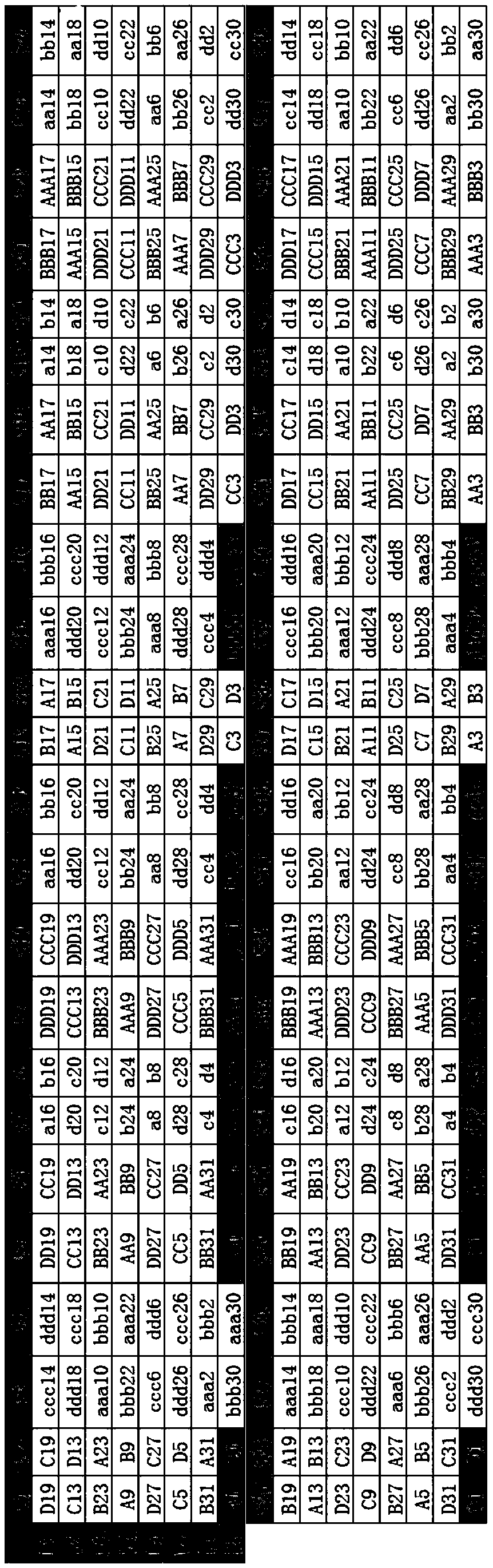
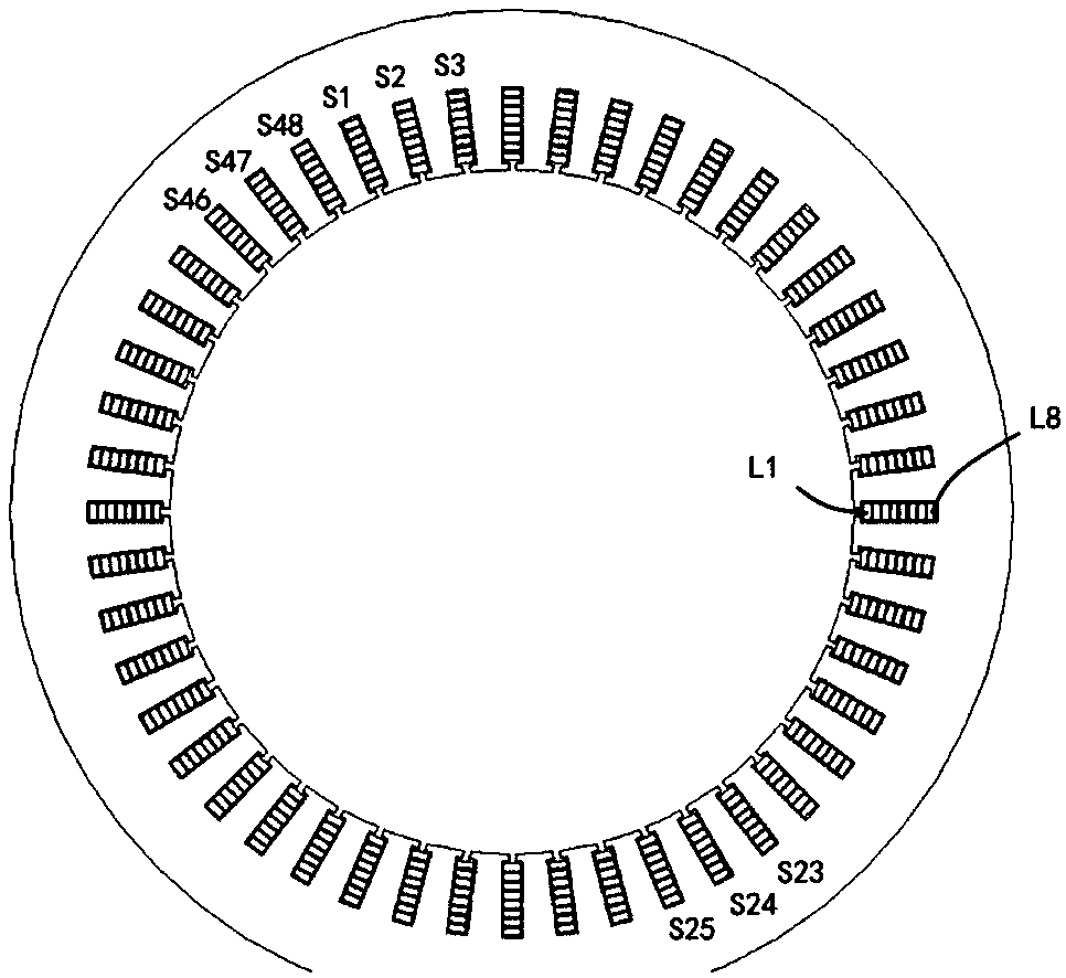
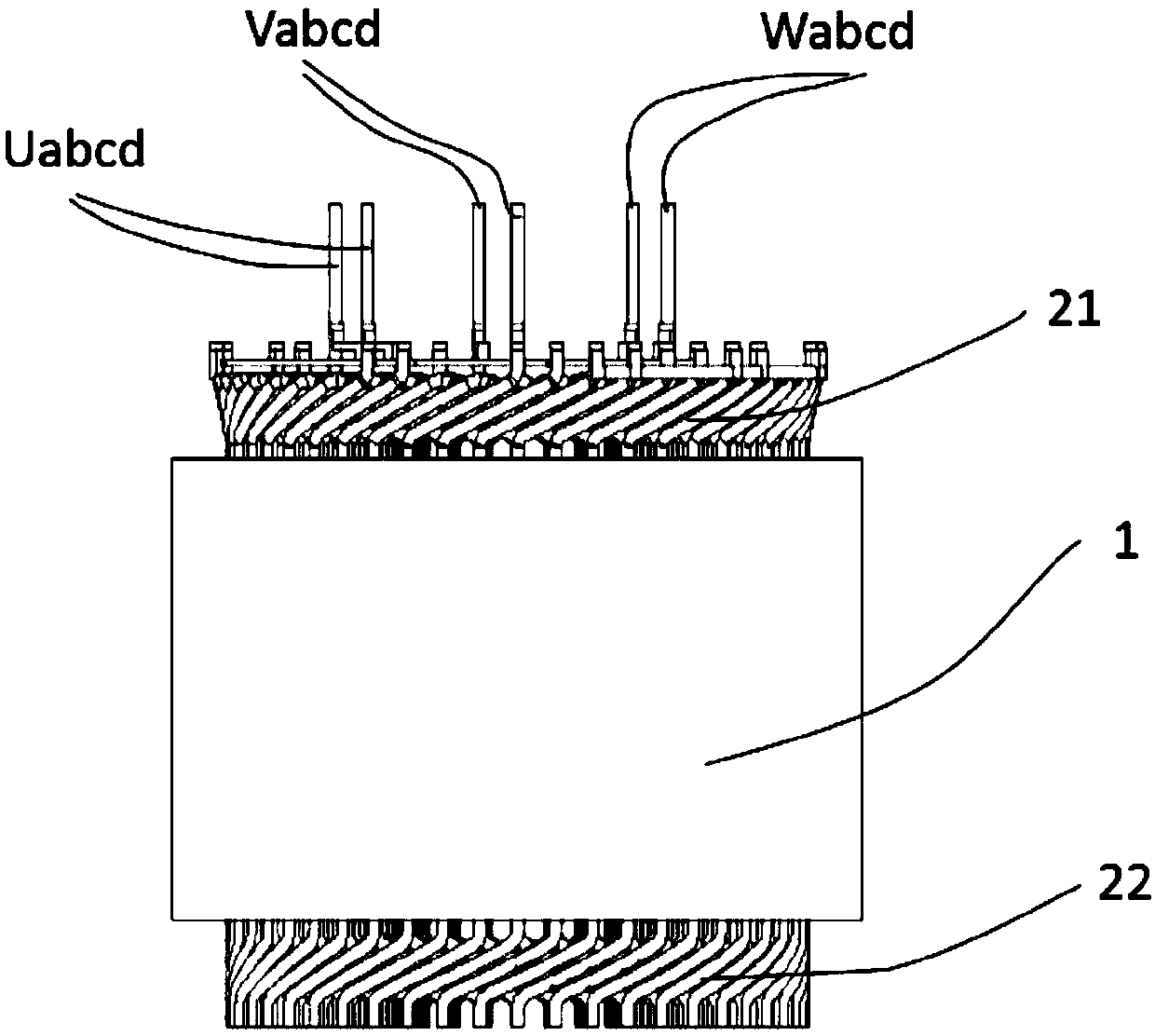
[0029] as attached Figure 1-6 As shown, a four-way parallel flat wire motor winding structure includes a stator core, and wire slots are opened on the teeth of the stator core. The flat copper wires are embedded in the corresponding slots according to the distribution method of the three-phase windings, and 48 slots are set on the inner ring of the stator core. figure 1 It is the winding connection diagram of the three-phase winding of the motor stator. Among them, S1, S2...S47, S48 represent the stator core slot number.

[0030] Each wire slot includes wire layers of 8 flat wires, and the flat copper wires are stacked and embedded sequentially along the radial direction of the stator core to form windings, and the wire layers are sorted in ascending order along the direction away from the center of the circle. Such as figure 1 As shown, L1, L2...L7, L8 represent the number of layers in each wire slot, and the wire layers are sequentially away from the center of the circle...


PUM


Abstract

The invention discloses a winding structure of a four-path parallel flat wire motor, which comprises a stator core, and is characterized in that wire slots are formed in a tooth part of the stator core; flat copper wires are embedded into the corresponding wire slots according to a three-phase winding distribution method, and 48 wire slots are formed; each wire slot includes wire layers of eight flat wires, the flat copper wires are sequentially stacked and embedded in the radial direction of the stator core to form a winding, and the wire layers are sorted in an ascending order in the direction away from the circle center; each phase of the winding comprises different parallel branches; each branch is provided with an output end and an input end; and each parallel branch enters and exitsfrom adjacent wire layers between different wire slots in sequence from the input end, the embedded position of the input end is taken as a sequence 1, the embedded position of the output end is takenas a sequence 32, and each passing embedded position is labeled in sequence. The structure does not generate circulating current, widens the selection space of the number of turns of windings and thenumber of parallel branches in the motor scheme design stage, facilitates the optimization of the motor design scheme, and better meets the requirements of motor performance and temperature rise.

Description

technical field [0001] The invention relates to the field of motor structure, in particular to a winding structure of a four-way parallel flat wire motor. Background technique [0002] Flat wire motor windings are generally connected by several square conductors by welding. The number of square conductors in the stator core slot of an automobile motor is generally 2, 4, 6 or 8, and the number of parallel branches of the winding is generally 1 or 2. Therefore, the design flexibility of the number of winding turns and the number of parallel branches is poor, which is not conducive to optimizing the design scheme of the motor. [0003] The number of parallel branches of flat wire windings in the prior art is generally 1 or 2. The winding methods of 1 parallel and 2 parallel can easily eliminate circulating current and the winding process is relatively simple, but there are other adverse effects. For example, under the condition of a certain DC bus voltage of the motor, a smal...

Claims


Application Information

Patent Timeline
Patent Type & Authority Applications(China)
IPC IPC(8): H02K3/28H02K3/12H02K3/14
CPCH02K3/12H02K3/14H02K3/28
Inventor 刘蕾朱标龙王锐
Owner HEFEI JUYI POWER SYST CO LTD
Why Eureka
Try Eureka