
Rotor short-circuit ring casting mold

A technology for short-circuiting the rotor and casting molds, which is applied in the directions of rotors, stators, engine components, etc., can solve the problems of unstable quality, poor quality, and unfavorable industrial production and manufacturing.

Inactive Publication Date: 2020-05-29
CHENG CHANG MACHINE ELECTRONIC CORP
View PDF10 Cites 0 Cited by
  • Summary
  • Abstract
  • Description
  • Claims
  • Application Information

AI Technical Summary

Problems solved by technology

[0004] The manufacturing method of the above-mentioned short-circuit ring 93 has great disadvantages, because the middle of the stack of short-circuit ring copper sheets 931 may not be tightly bonded, there must be gaps, and each piece of short-circuit ring copper sheet 931 must be welded once. It is quite slow, which is not conducive to the production and manufacturing of the industry, and the quality cannot be stabilized, and the yield and efficiency are not good.

Method used


Image

  • Rotor short-circuit ring casting mold
  • Rotor short-circuit ring casting mold
  • Rotor short-circuit ring casting mold

Examples


Embodiment Construction

[0031] Please refer to the relevant drawings below to further describe the embodiment of the casting mold structure of the rotor short-circuit ring of the present invention. In order to facilitate the understanding of the implementation of the present invention, the same components are described below with the same symbols.

[0032] The accompanying drawings are for illustration purposes only and are not drawn to original scale. On the other hand, well-known components and steps have not been described in the embodiments in order not to limit the invention unnecessarily.

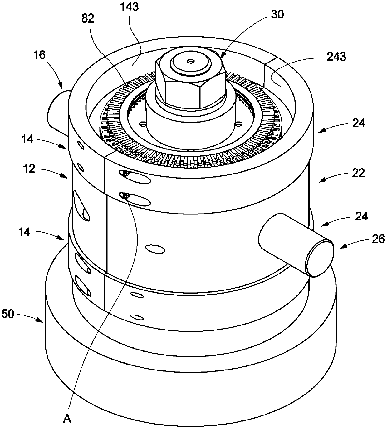
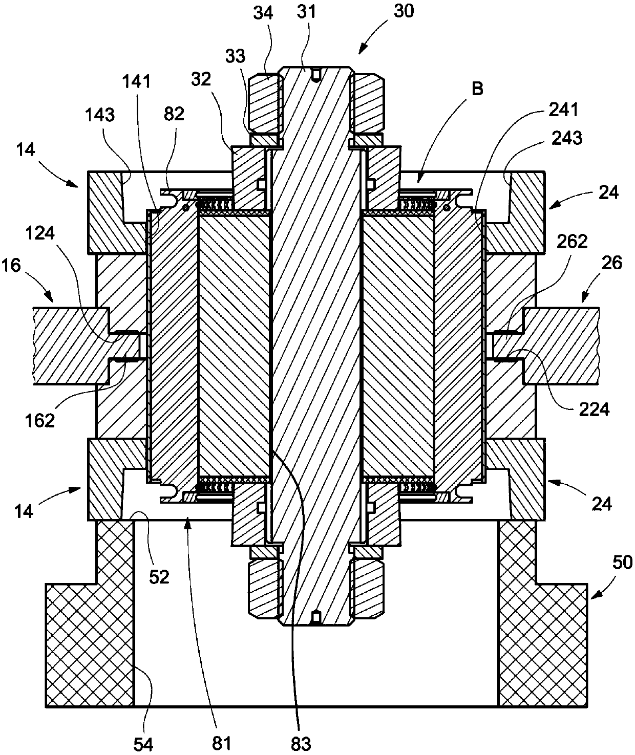
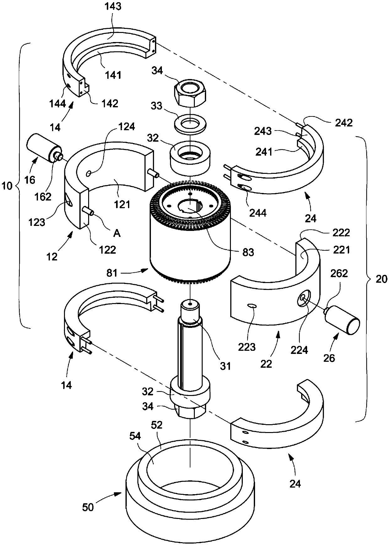
[0033] see Figures 1 to 4 As shown, the rotor short-circuit ring casting mold of the present invention is used to clamp the iron core 81 radially outer peripheral side of a squirrel cage rotor, surround the iron core 81 and each conductive copper sheet 82 protruding from the end face of the iron core, so as to facilitate The casting process includes a left module 10 , a right module 20 , a center axis modu...


PUM


Abstract

The invention discloses a rotor short-circuit ring casting mold. The rotor short-circuit ring casting mold comprises a left mold block, a right mold block, a central shaft mold block and a bearing seat, wherein the central shaft module penetrates through an iron core shaft hole of a rotor and cooperates with the left mold block and the right mold block to clamp and hold the radial peripheral sideof an iron core so as to surround the iron core and protrude out of all conductive copper sheets at the end face of the iron core, and a casting area is defined at each of the two axial ends of the iron core. By means of the composition of the components, the casting process is facilitated, and the short-circuit rings integrally formed with the free ends of all the conductive copper sheets are cast at the two axial ends of the iron core.

Description

technical field [0001] The invention relates to the technical field related to casting technology, in particular to a rotor short-circuit ring casting mold. Background technique [0002] In the design of the motor, in addition to using the change of the AC phase to generate a changing magnetic field, it can also use the changing surrounding magnetic field to induce the intermediate rotor to generate a magnetic field, so that the rotor does not need to be wound with coils, and does not need to have carbon brushes and other structures. instead simplifies rotor construction, see Figure 6 , 7 As shown, for the squirrel cage rotor of an induction motor (single-phase and three-phase), the conductive copper sheet 92 (or rod) is interspersed in the stacked silicon steel sheet core 91, and the two ends are turned into a squirrel cage by using a short-circuit ring 93. The surrounding fluctuating magnetic field is induced to generate eddy current and magnetic force to rotate. [000...

Claims


Application Information

Patent Timeline
Patent Type & Authority Applications(China)
IPC IPC(8): B22D19/04
CPCB22D19/0054B22D19/04
Inventor 彭昭群
Owner CHENG CHANG MACHINE ELECTRONIC CORP
Learn More