
Mirror milling equipment and method for thin-walled parts based on non-contact support

A technology of mirror milling and thin-walled parts, which is applied in the direction of milling machine equipment, milling machine equipment details, metal processing equipment, etc., can solve problems such as overcut or scratches, and achieve the effect of avoiding overcut phenomenon

Active Publication Date: 2020-11-03
INST OF MACHINERY MFG TECH CHINA ACAD OF ENG PHYSICS
View PDF5 Cites 1 Cited by
  • Summary
  • Abstract
  • Description
  • Claims
  • Application Information

AI Technical Summary

Problems solved by technology

[0010] The purpose of the present invention is to provide thin-wall mirror milling equipment and method based on non-contact support, so as to solve the problem of overcut or scratch caused by existing mirror milling technology

Method used

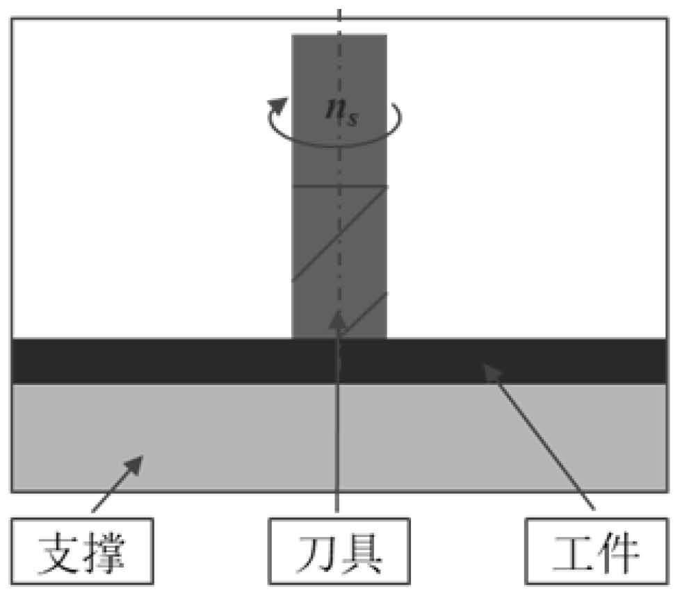
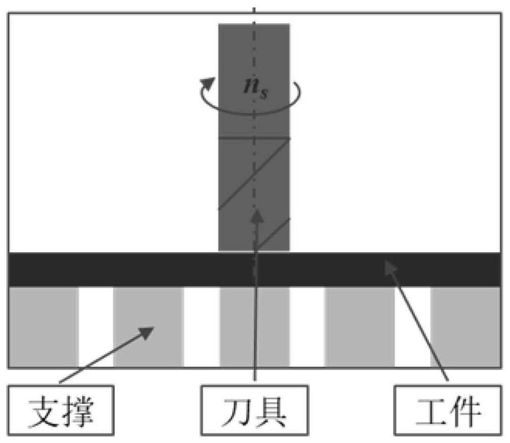
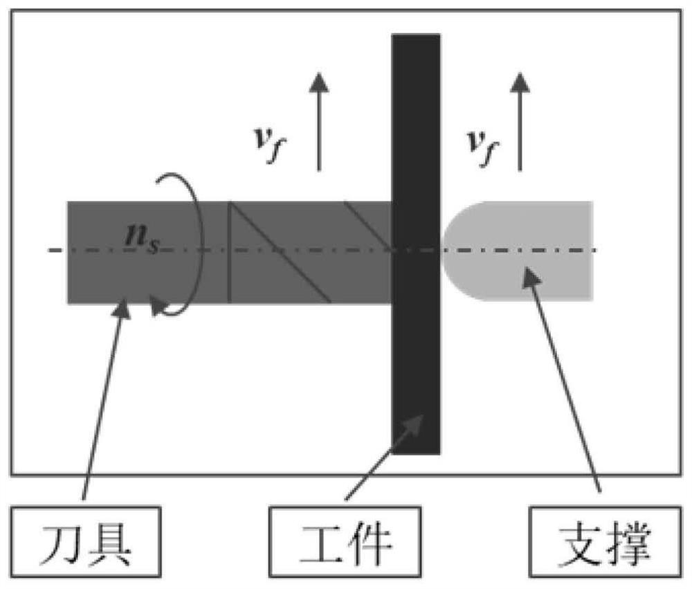

Image

  • Mirror milling equipment and method for thin-walled parts based on non-contact support
  • Mirror milling equipment and method for thin-walled parts based on non-contact support
  • Mirror milling equipment and method for thin-walled parts based on non-contact support

Examples


Embodiment 1

[0043] Such as Figure 8 As shown, the mirror milling equipment for thin-walled parts based on non-contact support includes a milling system, a workbench 12 and a support system. The workbench 12 is used to install a thin-walled part 4. Between the systems, the milling system includes a main shaft 2, the end of the main shaft 2 is equipped with a milling cutter 3, the support system includes a support head 5, and the milling system also includes a sensor 1, and the support head 5 is on the shaft There is a central through hole upward, and it also includes an air supply system and an industrial computer 9 for automatic control. The air supply system includes a pipeline, and one end of the pipeline communicates with the central through hole, and the other end communicates with the central air supply system. The system is connected, and a pump 7 and a valve 11 are arranged on the pipeline;

[0044] The sensor 1 is used to collect the cutting force signal of the milling cutter 3,...

Embodiment 2

[0052] Such as Figure 8 As shown, this embodiment is based on Embodiment 1, and a filter 8 , a flow meter 6 and a pressure gauge 10 are arranged on the pipeline.


PUM


Abstract

The invention discloses thin-walled part mirror image milling equipment and method based on follow-up non-contact support. The thin-walled part mirror image milling equipment comprises a milling system, a working table and a supporting system, wherein the milling system involves a main shaft, a milling cutter is mounted at the end part of the main shaft, the supporting system involves a supportinghead, the milling system further involves a sensor, a central through hole is formed in the supporting head in the axial direction, the thin-walled part mirror image milling equipment further involves an air supplying system and an industrial personal computer for achieving automatic control, and a pump and a valve are mounted in the air supplying system. In the cutting process, the force millingdirection and the amplitude data of the milling cutter are collected in real time by a sensor, and under the working condition that the axial cutting depth is small, the central through hole of the supporting head generates thrust to a thin-walled part through a high-pressure air flow flowing to the back surface of the thin-walled part to prevent the thin-walled part and the milling cutter from separating, so that the occurrence of the impact vibration is avoided; and under the working condition that the axial cutting depth is large, the central through hole of the supporting head generates tension to the thin-walled part through a high-pressure air flow away from the back surface of the thin-walled part, so that the occurrence of overcutting is avoided.

Description

technical field [0001] The invention relates to the field of high-efficiency and high-precision machining of weakly rigid thin-walled components, and in particular to mirror milling equipment and methods for thin-walled parts based on non-contact support. Background technique [0002] Thin-walled structures are widely used in aerospace engineering for the purpose of reducing the weight of the spacecraft and improving the carrying capacity. The characteristics of these thin-walled structures include large spatial dimensions and complex shapes. In the early days, due to the backward processing technology, these thin-walled structures were usually processed by step-by-step manufacturing, and then assembled and formed, that is, a complex large-scale structural part was usually decomposed into many parts with simple topology and easy processing. After the parts of the structure are machined, the final thin-walled structure is obtained by welding or riveting. It is difficult to e...

Claims


Application Information

Patent Timeline
Patent Type & Authority Patents(China)
IPC IPC(8): B23C3/00B23Q11/00
CPCB23C3/00B23Q11/00B23Q11/0032
Inventor 费基雄黄文孔金星张晓峰徐飞飞杜东兴任松张思琪汤金钢陈一
Owner INST OF MACHINERY MFG TECH CHINA ACAD OF ENG PHYSICS
Learn More