3D vapor deposition male spin coating pot structure

A technology of revolution and evaporation, which is applied in the directions of vacuum evaporation plating, sputtering plating, ion implantation plating, etc., can solve the problems of poor step coverage, inconsistent coating structure, and inability to provide linear operation, etc., to achieve stable structural support , better coating thickness uniformity

Active Publication Date: 2022-03-08
HERMES EPITEK
View PDF5 Cites 0 Cited by
  • Summary
  • Abstract
  • Description
  • Claims
  • Application Information

AI Technical Summary

Problems solved by technology

[0012] The present invention is a male-rotating coating pot structure for 3D evaporation, which mainly solves the problems caused by unstable support of the coating pot structure, inability to provide linear operation, and poor design of the evaporation angle when the coating pot performs evaporation on wafers. Poor coating thickness uniformity, poor step coverage, and inconsistent coating structure

Method used


Image

  • 3D vapor deposition male spin coating pot structure
  • 3D vapor deposition male spin coating pot structure
  • 3D vapor deposition male spin coating pot structure

Examples


Embodiment Construction

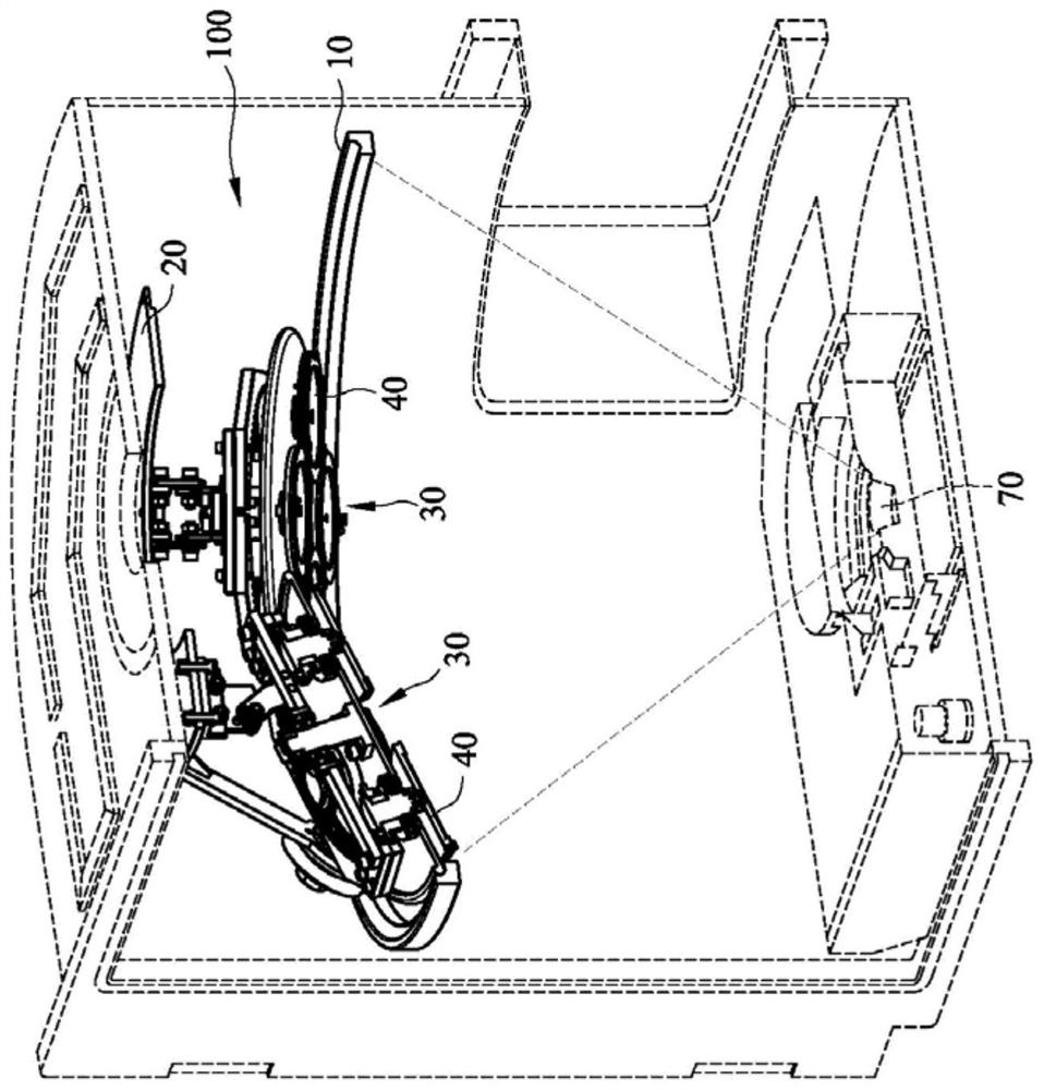
[0058] Such as Figure 2 to Figure 4 As shown, the present embodiment is a male-rotating coating pot structure 100 for 3D evaporation, which includes: a revolving bottom plate 10 ; a revolving top plate 20 ; a plurality of coating pot rotation modules 30 ; and a plurality of wafer carriers 40 .

[0059] The revolving base 10 is used as the bottom support of the entire revolving coating pot structure 100 , and in order to achieve the effect of rotation, the revolving base 10 can be a circular orbit.

[0060] The revolving top plate 20 has a plurality of supports 210 so that the revolving top plate 20 can be erected on the revolving chassis 10 . In order to make the revolving top plate 20 rotate effectively, a revolving wheel 220 can be provided at the bottom of each supporting member 210 . The revolving top plate 20 can smoothly run around the revolving chassis 10 by means of the revolving runner 220 .

[0061]In order to allow the revolving top plate 20 to be arranged on the...


PUM


Abstract

The present invention is a 3D evaporation coating pot structure, which includes: a revolving base plate; a revolving top plate runs around the revolving base plate by means of a support; a plating pot rotation module has a cantilever and is combined with the revolving top plate; and its gears The disc is combined with the bottom side of the cantilever; its self-rotating plating disc is combined with the cantilever and runs around in a circular orbit; and a plurality of wafer carriers are fixed on the self-rotating plating disc by the rotating shaft, and the outer ring shape The teeth are combined with the rotation of the gear disc.

Description

technical field [0001] The present invention is a 3D vapor deposition male spin coating pot structure, in particular a 3D vapor deposition male spin coating pot structure using semiconductor wafer vapor deposition. Background technique [0002] China Taiwan Patent Announcement No. 00470215 (hereinafter referred to as Patent No. 215), discloses a fixed structure of a public and self-rotating wafer carrier, which mainly discloses a revolution frame and a rotatable wafer carrier P13, but there are The following questions: [0003] 1. There are only two rotation axes P110 and P120, and the wafer cannot rotate during evaporation, which will cause shadows due to directionality and cause inconsistent film thickness. [0004] 2. The wafer carrier P13 must be driven by the shaft AP131 to rotate, and the shaft AP131 plus the driving unit that must rotate accordingly will increase the volume of the equipment. [0005] 3. The entire wafer carrier P13 must be supported by the roller P1...

Claims


Application Information

Patent Timeline
Patent Type & Authority Patents(China)
IPC IPC(8): C23C14/24C23C14/50
CPCC23C14/24C23C14/505
Inventor 陈家璧薛文皓罗世欣
Owner HERMES EPITEK
Why Eureka
Try Eureka