
Full-variable electro-hydraulic valve system

A valve and variable technology, applied in the direction of non-mechanical actuated valves, engine components, machines/engines, etc., can solve the problems of constant crankshaft angle, oil loss, and affecting the normal operation of the system, and achieve fast response and control convenient effect

Pending Publication Date: 2020-05-29
WEIFANG LICHUANG ELECTRONICS TECH
View PDF1 Cites 2 Cited by
  • Summary
  • Abstract
  • Description
  • Claims
  • Application Information

AI Technical Summary

Problems solved by technology

[0006] Aiming at the above-mentioned shortcomings of the prior art, the present invention provides a fully variable electro-hydraulic valve system to solve the problem that the normal operation of the system is affected by the loss of oil in the sliding sleeve cavity, and to make the crank angle corresponding to the opening moment of the valve constant

Method used


Image

  • Full-variable electro-hydraulic valve system
  • Full-variable electro-hydraulic valve system
  • Full-variable electro-hydraulic valve system

Examples


Embodiment Construction

[0034] The present invention will be further described below in conjunction with the accompanying drawings and embodiments.

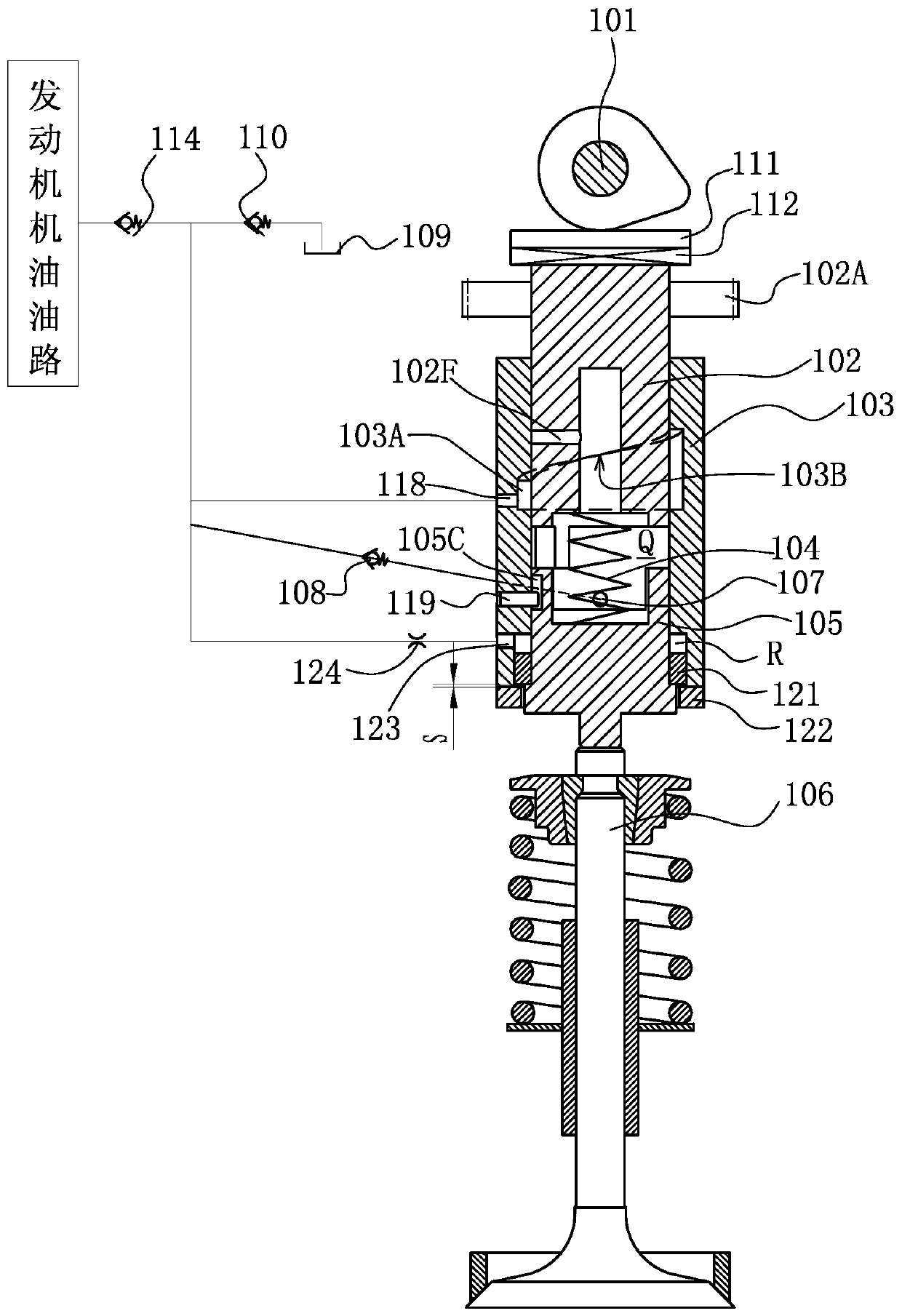
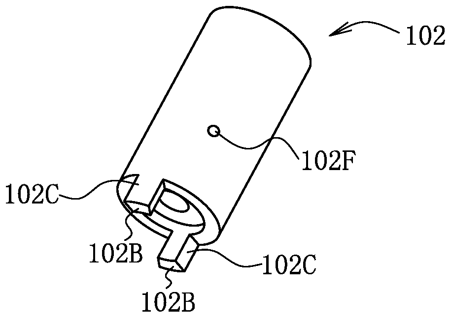
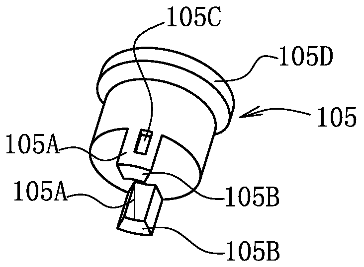
[0035] Such as figure 1 As shown, a fully variable electro-hydraulic valve system, the sliding sleeve 103 is fixed relative to the engine, the sliding shaft 102 and the piston 105 are respectively in sliding and sealing connection with the sliding sleeve 103, and the sliding shaft 102 is controlled by the direction of the camshaft 101 in the axial direction. The piston 105 abuts against the valve assembly 106 on the cam surface.

[0036] In the sliding sleeve 103, the space between the sliding shaft 102 and the piston 105 is the sliding sleeve cavity Q, the return spring 104 is clamped between the sliding shaft 102 and the piston 105, and the joint force of the return spring 104 and the oil pressure on the piston 105 Far less than the force of the valve spring on the piston 105. The sliding sleeve 103 is provided with an oil inlet hole 107 and an oil...


PUM


Abstract

The invention discloses a full-variable electro-hydraulic valve system. The system comprises a sliding sleeve, a sliding shaft, a piston and a reset spring; the sliding sleeve is fixed relative to anengine, the piston abuts against a valve assembly, and the sliding shaft is axially controlled by a cam surface of a camshaft; the sliding shaft is provided with a limiting oil hole which communicateswith a sliding sleeve cavity, the inner hole wall of the sliding sleeve is provided with a spiral groove, the spiral groove communicates with an oil through hole, and when the spiral groove communicates with the limiting oil hole, the sliding sleeve cavity communicates with a low-pressure oil way of the engine for pressure relief; and an axial protruding part of the sliding shaft is provided witha sliding shaft abutting plane, and the head part of an axial protruding part of the piston is provided with a piston abutting plane. The system solves the problem that the normal operation of the system is influenced due to oil loss in the sliding sleeve cavity, keeps a crank angle corresponding to the valve opening time unchanged, and is particularly suitable for controlling the variable strokeof an intake valve of the engine with a scavenging process.

Description

technical field [0001] The invention relates to the technical field of engine valve mechanism, in particular to a fully variable electro-hydraulic valve system. Background technique [0002] Fully Variable Valve System (FVVS for short) can realize the continuous variable of the maximum valve lift, valve opening duration angle and valve timing, which is of great significance to the energy saving and emission reduction of the engine. FVVS can control the amount of working fluid entering the cylinder by means of early intake valve closing (EIVC), thereby canceling the throttle valve. This throttleless gasoline engine will greatly reduce the pumping loss and reduce the fuel consumption under small and medium loads. 10-15%. The fully variable valve mechanism is matched with supercharging and intercooling, which can solve the problems of engine deflagration and high heat load after supercharging, realize low-temperature combustion under the premise of greatly increasing the avera...

Claims


Application Information

Patent Timeline
IPC IPC(8): F01L9/02F01L13/00F01L9/10
CPCF01L13/00F01L9/14
Inventor 王立峰王秀强王孟晓吴龙龙从田增王昊天吴贝贝吴鹏超衣金水苏明涛
Owner WEIFANG LICHUANG ELECTRONICS TECH
Features
  • Generate Ideas
  • Intellectual Property
  • Life Sciences
  • Materials
  • Tech Scout
  • Unparalleled Data Quality
  • Higher Quality Content
  • 60% Fewer Hallucinations
Learn More