Eureka AIR delivers breakthrough ideas for toughest innovation challenges, trusted by R&D personnel around the world.

Signal demodulation system and signal demodulation method

A signal demodulation and signal technology, applied in FM carrier system, modulated carrier system, transmission system, etc., can solve the problems of non-coherent demodulation of FM signal, low frequency band utilization, and coherent demodulation of modulation coefficient at the receiving end. Achieve the effect of eliminating influence and ensuring stability

Active Publication Date: 2020-05-29
PHYPLUS INC
View PDF7 Cites 2 Cited by
  • Summary
  • Abstract
  • Description
  • Claims
  • Application Information

AI Technical Summary

Problems solved by technology

The usual receiving end cannot perform coherent demodulation for changing modulation coefficients. During the demodulation process of FM signals, the residual frequency offset in the FM signal needs to be considered. The existence of these residual frequency offsets makes the demodulation process of FM signals not coherent demodulation. , thus affecting the demodulation result of the FM signal
In the existing schemes, non-coherent demodulation methods are mostly adopted, such as split filter envelope detection method, zero-crossing detection method, etc., but these methods have low frequency band utilization and are difficult to accurately detect

Method used


Image

  • Signal demodulation system and signal demodulation method
  • Signal demodulation system and signal demodulation method
  • Signal demodulation system and signal demodulation method

Examples


Embodiment Construction

[0017] In order to make the purpose, technical solutions and advantages of the embodiments of the present invention more clear, various implementation modes of the present invention will be described in detail below in conjunction with the accompanying drawings. However, those of ordinary skill in the art can understand that, in each implementation manner of the present invention, many technical details are provided for readers to better understand the present application. However, even without these technical details and various changes and modifications based on the following implementation modes, the technical solution claimed in this application can also be realized. The division of the following embodiments is for the convenience of description, and should not constitute any limitation to the specific implementation of the present invention, and the various embodiments can be combined and referred to each other on the premise of no contradiction.

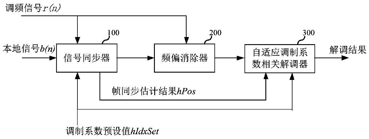
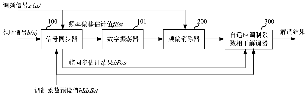
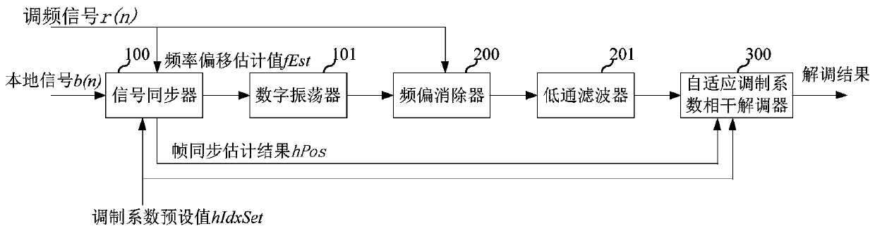
[0018] A first embodime...


PUM


Abstract

The embodiment of the invention relates to the field of communication, and discloses a signal demodulation system and demodulation method, and the system comprises a signal synchronizer which is usedfor calculating a frequency offset estimation value and a frame synchronization estimation result according to an inputted frequency modulation signal and a local signal, a frequency offset eliminatorwhich is used for eliminating estimated residual frequency offset in the frequency modulation signal according to the frequency offset estimation value to obtain a first signal, and an adaptive modulation coefficient coherent demodulator which is used for outputting a demodulation result of the frequency modulation signal according to the first signal and the frame synchronization estimation result, wherein the modulation coefficient of the signal synchronizer and the modulation coefficient of the adaptive modulation coefficient coherent demodulator are preset to be the same coefficient value, and different coefficient values correspond to different demodulation frameworks. According to the invention, the modulation coefficient of the signal synchronizer and the modulation coefficient ofthe adaptive modulation coefficient coherent demodulator are preset to be the same coefficient value, and different coefficient values correspond to different demodulation frameworks, so that coherentdemodulation is realized, and the influence caused by the changed modulation coefficient is eliminated.

Description

technical field [0001] The embodiments of the present invention relate to the communication field, and in particular to a signal demodulation system and demodulation method. Background technique [0002] The FSK (Frequency Shift Keying) signal is a signal used for high-speed data transmission. The transmitting end of the FSK modulated signal usually sets a range for the FSK modulation coefficient. For example, the FSK modulation coefficient of the BT architecture is usually set to 0.28-0.35, and the FSK modulation coefficient of the BLE architecture is usually set to 0.45-0.55. The usual receiving end cannot perform coherent demodulation for changing modulation coefficients. During the demodulation process of FM signals, the residual frequency offset in the FM signal needs to be considered. The existence of these residual frequency offsets makes the demodulation process of FM signals not coherent demodulation. , thus affecting the demodulation result of the FM signal. In t...

Claims


Application Information

Patent Timeline
Patent Type & Authority Applications(China)
IPC IPC(8): H04L27/10H04L27/14H04L27/152H04L27/26H04L27/00
CPCH04L27/10H04L27/14H04L27/152H04L27/0014H04L27/2656H04L2027/0026
Inventor 杨中奇
Owner PHYPLUS INC
Why Eureka
Eureka Blog
Learn More