
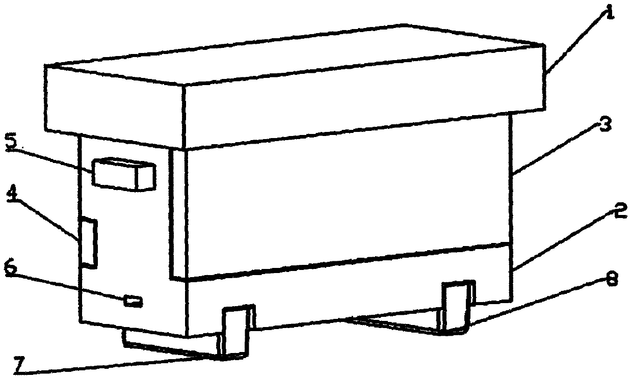
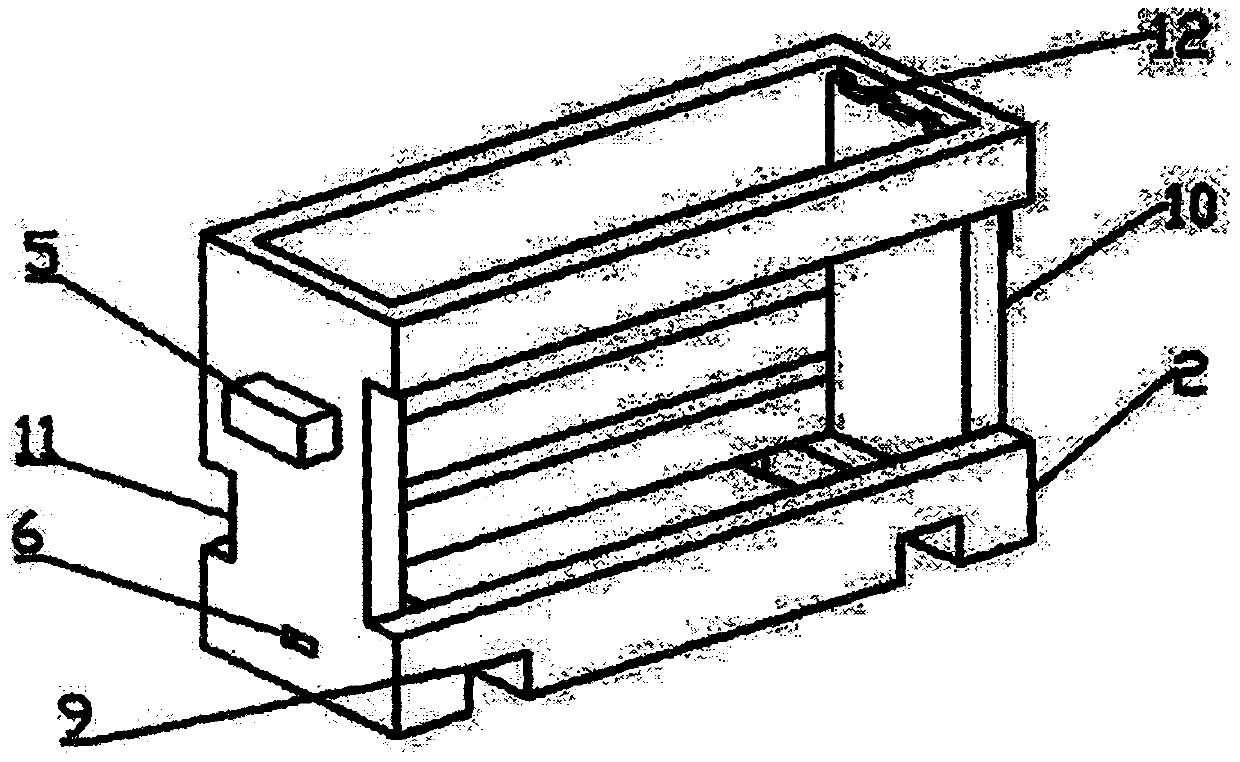
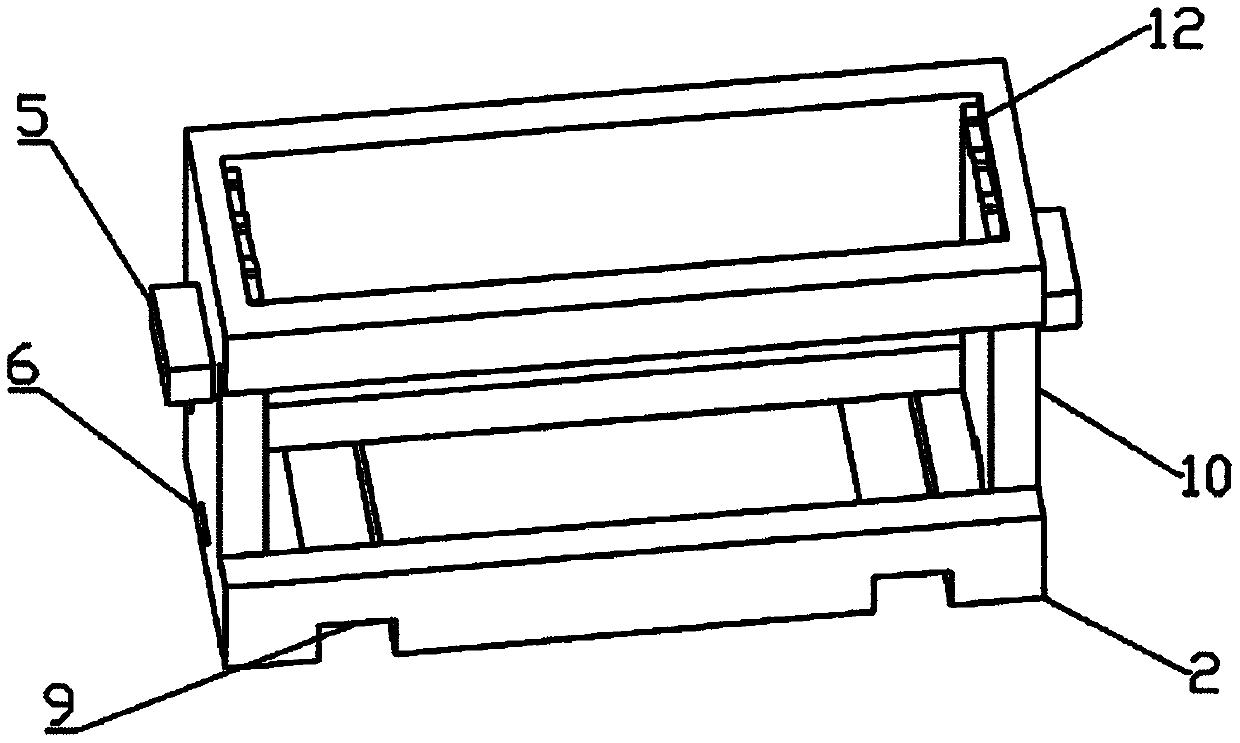
Tail band type feeding pollination bee observation box applied to facility crops

A facility crop and observation box technology, applied in beehives, applications, beekeeping, etc., can solve the problems of increasing costs, disturbing bee colonies, solving bee colony feed, pollen and ventilation, etc., achieving long-term use and saving money. Effect

Pending Publication Date: 2020-06-02
吉林省养蜂科学研究所
View PDF0 Cites 0 Cited by
  • Summary
  • Abstract
  • Description
  • Claims
  • Application Information

AI Technical Summary

Problems solved by technology

At present, the beehives used by bees to pollinate facility crops are various and of different materials. However, during the pollination process, the beehives must be regularly opened to check the bee colony. Due to human interference, the pollination time of the bee colony is shortened. , increasing the cost
However, in the current existing beehives, it is impossible to meet the needs of bee colony feed, pollen and ventilation outside the beehive, and it will artificially interfere with the order of bee colony formation and pollination of facility crops during breeding, affecting the development and health of bee colony offspring. Conventional pollination The box is opened from the bottom of the beehive, so that cold and hot air directly enter the center of the hive, which has a greater impact on the ambient temperature inside the bee colony. pollination, and people are easily stung by bees, in view of this, in order to efficiently use bees to pollinate facility crops, it is necessary to design a bottom-belt feeding pollination bee observation box for facility crops to solve the problems in the prior art

Method used


Image

  • Tail band type feeding pollination bee observation box applied to facility crops
  • Tail band type feeding pollination bee observation box applied to facility crops
  • Tail band type feeding pollination bee observation box applied to facility crops

Examples


Embodiment Construction

[0033] The following will clearly and completely describe the technical solutions in the embodiments of the present invention with reference to the accompanying drawings in the embodiments of the present invention. Obviously, the described embodiments are only some, not all, embodiments of the present invention. Based on the embodiments of the present invention, all other embodiments obtained by persons of ordinary skill in the art without making creative efforts belong to the protection scope of the present invention.

[0034] In order to make the above objects, features and advantages of the present invention more comprehensible, the present invention will be further described in detail below in conjunction with the accompanying drawings and specific embodiments.

[0035] refer to Figure 1-8 , the present invention provides a bottom-belt type feeding and pollination bee observation box for facility crops, comprising a large beehive cover 1, a box mechanism, a ventilation me...


PUM

PropertyMeasurementUnit
Densityaaaaaaaaaa

Abstract

The invention provides a tail band type feeding pollination bee observation box applied to facility crops. The observation box comprises a big bee hive cover, a box mechanism, a ventilation mechanism,an observation window mechanism and a tail band type feeding mechanism; the big bee hive cover is buckled above the box mechanism; the box mechanism comprises a box, a ventilation opening and an observation window are formed in two long side surfaces of the box respectively, a hive door is formed on the narrow side surface of the box, two through grooves are formed in the bottom of the box, and aplurality of tooth grooves are formed in the top ends of the inner walls of two narrow side surfaces of the box; the ventilation mechanism is arranged in the ventilation opening, and the observationwindow mechanism is arranged in the observation window; and the tail band type feeding mechanism comprises a pollen feeding tank and a sweet water feeding tank which are arranged in the two through grooves respectively. Demands of swarm feed, pollens and ventilation can be met outside the bee hive, the order of swarms for pollination of the facility crops is not artificially disturbed, swarm offsprings develop healthily, and utilization time of swarm pollination is long.

Description

technical field [0001] The invention relates to the technical field of bee breeding, in particular to a bottom-belt type feeding pollination bee observation box for facilities crops. Background technique [0002] Bee pollination is a technical measure to increase agricultural production developed in modern times. The use of bee pollination can not only increase the seed setting rate of crops, but also enhance the vitality of crops through cross-pollination, so as to achieve the purpose of increasing production. At present, bee pollination has developed into a beekeeping technology. important parts of. [0003] Since facility agriculture is organized under a controlled environment, the crops are planted in a closed environment with poor air circulation and no pollinators. The pollination of some insect- and wind-pollinated crops will be greatly affected, resulting in low fruit setting and low yield. Low, low quality poor. In order to help pollination of facility crops, a va...

Claims


Application Information

Patent Timeline
IPC IPC(8): A01K47/00A01K47/02A01K47/06A01K53/00A01H1/02
CPCA01H1/02A01K47/00A01K47/02A01K47/06A01K53/00
Inventor 李杰銮薛运波常志光刘玉玲
Owner 吉林省养蜂科学研究所
Learn More