Distal radius functional splint

A splint and distal technology, which is applied in the field of medical devices, can solve the problems of inconvenient control of the heating temperature of the radial bone, poor ventilation of the functional splint at the distal radial end, radial head fracture or lower end fracture, etc., so as to ensure the effect of medication, Improve experience and reduce power consumption

Inactive Publication Date: 2020-06-02
滁州先奇工业科技有限公司
View PDF8 Cites 0 Cited by
  • Summary
  • Abstract
  • Description
  • Claims
  • Application Information

AI Technical Summary

Problems solved by technology

[0002] With the development of society and the improvement of living standards, people pay more and more attention to their health. The radius is an important part of the arm. The radius is located on the outer side of the forearm. It is divided into two ends. The concave is jointed with the capitulum of the humerus; the surrounding annular articular surface is jointed with the ulnar joint; the lower part of the head is slightly thinner, called the inner and lower side of the radial neck, and there is a protruding radial tuberosity. The interosseous border, the lower end is concave and kyphosis, the outer side protrudes downward, called the styloid process, the inner surface of the lower end has an articular surface, called the ulnar notch, which articulates with the head of the ulna, and the lower end has a wrist articular surface that articulates with the carpal bone. When stretched on the ground, indirect violence can cause radial head fracture or lower end fracture. Distal radius fracture refers to the fracture within 3cm from the articular surface of the distal radius. 6. After reduction of the distal radius fracture, the commonly accepted fixation method is wrist joint ulnar deviation and palmar flexion. The existing functional splint of the distal radius has poor ventilation, which is not convenient for ventilation at the radius, which is not conducive to the fracture of the radius. Rehabilitation, it is inconvenient to control the heating temperature of the radial bone when taking medication, which affects the effect of medication. Therefore, it is urgent to develop a functional splint for the distal radial radius to solve the above problems and facilitate market promotion and application.

Method used


Image

  • Distal radius functional splint
  • Distal radius functional splint
  • Distal radius functional splint

Examples


Embodiment Construction

[0019] The following will clearly and completely describe the technical solutions in the embodiments of the present invention with reference to the accompanying drawings in the embodiments of the present invention. Obviously, the described embodiments are only some, not all, embodiments of the present invention. Based on the embodiments of the present invention, all other embodiments obtained by persons of ordinary skill in the art without making creative efforts belong to the protection scope of the present invention.

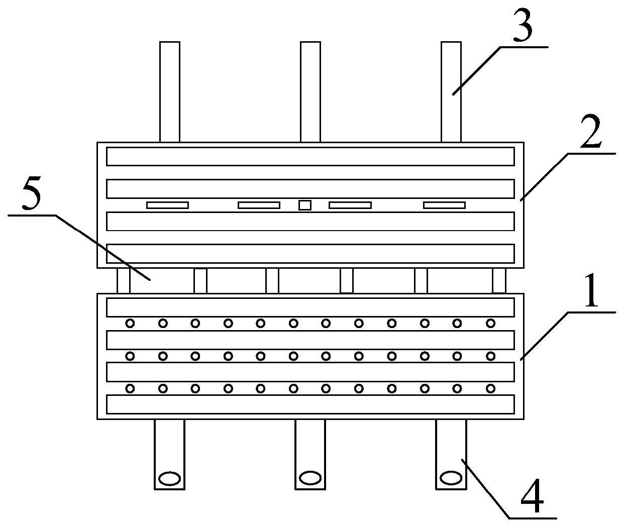
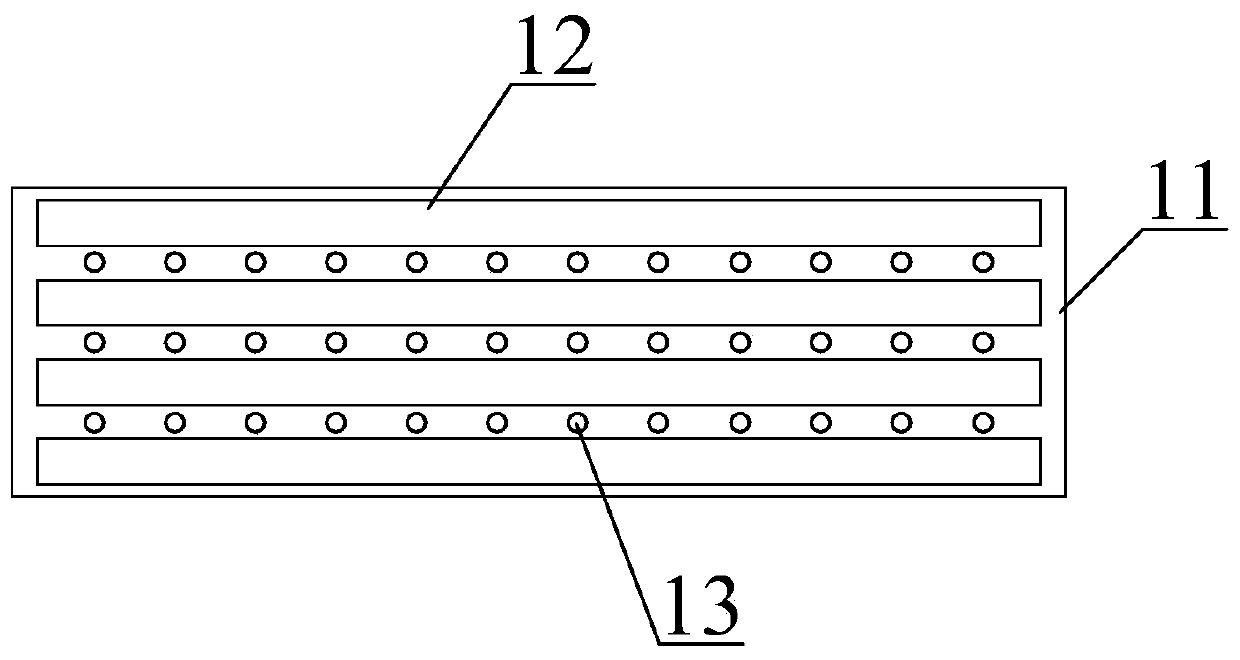
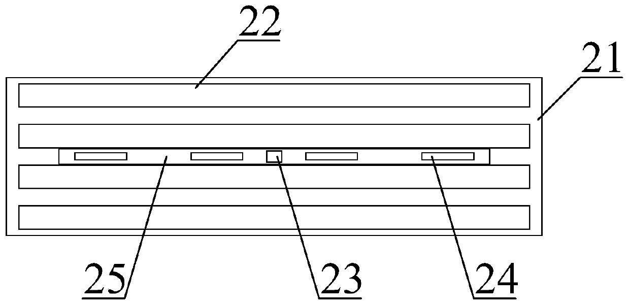
[0020] see Figure 1-4 , the present invention provides a technical solution: a functional splint for the distal end of the radius, such as figure 1 As shown, it includes a lower splint assembly 1, an upper splint assembly 2, a fastening belt 3, a fastening buckle 4 and a connecting belt 5. The upper splint assembly 2 is arranged above the lower splint assembly 1, and the upper splint assembly 2 passes through the connecting belt. 5 is connected with the lowe...


PUM


Abstract

The invention discloses a distal radius functional splint. The distal radius functional splint comprises a lower splint assembly, an upper splint assembly, fastening belts, fastening buttons and connecting belts. The lower splint assembly and the upper splint assembly are arranged, an upper splint and a lower splint form a functional splint, and through cooperation with first flexible belts and second flexible belts, a clamping operation on the radius of a user is performed, so that the comfort degree of the user can be increased; ventilation holes are convenient for convection of inside air and outside air, the ventilation property of the functional splint is guaranteed, ventilation of the radius position can be convenient, and rehabilitation of radius fracture is facilitated; the upper splint assembly is arranged, after medication, a button switch is pressed down, a heating plate is electrified to operate to heat the inner part of the functional splint, a temperature sensor is used for detecting the temperature value in the functional splint, when the temperature value reaches an upper limit value, the heating plate stops heating, and when the temperature value reaches a lower limit value, the heating plate is electrified for operations, so that the situation that the temperature value in the functional splint is in an appropriate range can be guaranteed, the medication effect can be guaranteed, and besides, the electricity consumption can be reduced.

Description

technical field [0001] The invention relates to the technical field of medical appliances, in particular to a functional splint for the distal end of the radial bone. Background technique [0002] With the development of society and the improvement of living standards, people pay more and more attention to their health. The radius is an important part of the arm. The radius is located on the outer side of the forearm. It is divided into two ends. The concave is jointed with the capitulum of the humerus; the surrounding annular articular surface is jointed with the ulnar joint; the lower part of the head is slightly thinner, called the inner and lower side of the radial neck, and there is a protruding radial tuberosity. The interosseous border, the lower end is concave and kyphosis, the outer side protrudes downward, called the styloid process, the inner surface of the lower end has an articular surface, called the ulnar notch, which articulates with the head of the ulna, and...

Claims


Application Information

Patent Timeline
Patent Type & Authority Applications(China)
IPC IPC(8): A61F5/058A61M37/00
CPCA61F5/05825A61F5/05866A61M37/00A61M2037/0007
Inventor 孙号
Owner 滁州先奇工业科技有限公司
Why Eureka
Try Eureka