
Integrated type fertilizer processing platform

A processing platform and integrated technology, applied in the field of machinery, can solve the problem of low efficiency of fertilizer sieving, and achieve high-efficiency sieving without affecting efficiency

Pending Publication Date: 2020-06-02
四川中农润泽生物科技有限公司
View PDF0 Cites 0 Cited by
  • Summary
  • Abstract
  • Description
  • Claims
  • Application Information

AI Technical Summary

Problems solved by technology

[0003] The purpose of the present invention is to provide an integrated fertilizer processing platform, which solves the problem of low efficiency of fertilizer screening

Method used


Image

  • Integrated type fertilizer processing platform
  • Integrated type fertilizer processing platform
  • Integrated type fertilizer processing platform

Examples


Embodiment 1

[0026] An integrated fertilizer processing platform provided by a preferred embodiment of the present invention,

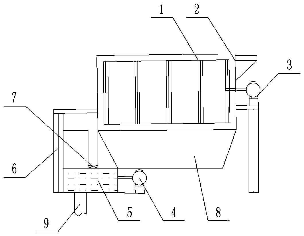
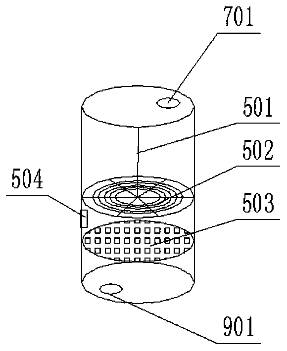
[0027] An integrated fertilizer processing platform, including a first crushing chamber 1, support columns 6 are arranged on both sides of the first crushing chamber 1, a first slag outlet 7 and a first discharge outlet 8 are arranged at the bottom, and a cylindrical The second crushing chamber 5, the second crushing chamber 5 is provided with a sieve tray 503 with small holes to divide its interior into upper and lower parts; the upper part includes a cover plate with a second feeding port 701, and the center of the cover plate is provided with a bottom connected to the grinding chamber. The lower part of the rotating shaft 501 of the disk 502 includes a bottom plate with a second discharge port 901 .

[0028] When working: the double crushing mode is adopted; after the crushing is qualified, it enters the first discharge port 8 or the second discharge port 901 t...

Embodiment 2

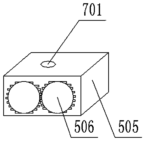
[0031] In this embodiment, on the basis of the first embodiment, a squeeze box 505 is provided below the second feed port 701, and the squeeze box 505 is rectangular and is located in the gap between the rotating shaft 501 and the side wall. The extrusion box 505 includes at least two extrusion rollers 506, and the extrusion rollers 506 are cylinders with convex teeth. The minimum gap between any two squeeze rollers 506 is larger than the diameter of the small hole of the sieve plate 503 . The first crushing chamber 1 includes a casing and a screen, and the screen is connected to the first motor 3 through a Pozidella frame assembly. The second material outlet 901 is connected with the material guide pipe 9 . The side wall of the second crushing chamber 5 is provided with a second slag outlet 504 that can be switched on and off, and the second slag outlet 504 is located above the sieve tray 503 .

[0032] When working: the squeeze box 505 does not affect the work of the rotat...


PUM


Abstract

The invention discloses an integrated type fertilizer processing platform. The integrated type fertilizer processing platform comprises a first smashing room, and further comprises a cylindrical second smashing room, wherein the two sides of the first smashing room are provided with supporting columns, and a first slag outlet and a second slag outlet are formed in the bottom of the first smashingroom; a sieve tray with a small hole is arranged in the second smashing room for dividing the inner part of the second smashing room into upper and lower parts; the upper part comprises a cover platewith a second charge hole; the center position of the cover plate is provided with a rotary shaft, the lower part of which is connected to a grinding disc; the lower part comprises a bottom plate witha second discharge hole; through primary rotary smashing and sieving of the first smashing room, qualified fertilizers are selected to enter the first discharge hole, so that the fertilizers enter anext process; and different form the conventional first smashing room, the conventional separated fertilizers are directly discharged from the first slag outlet or re-enter the first smashing room. According to the scheme adopted by the invention, a rotary smashing sieving method in the prior art is adopted, and the first slag outlet is connected to the second charge hole in the second smashing room to form re-filtration of waste.

Description

technical field [0001] The invention belongs to the field of machinery and relates to an integrated fertilizer processing platform. Background technique [0002] In the process of fertilizer production, the sieving of fertilizer is an essential process, which directly affects the quality and stability of fertilizer. At present, some fertilizer sieving methods use a single sieve. Due to the high viscosity of fertilizers and the different sizes of fertilizer particles when different fertilizers are mixed, it is not easy for the existing grinding device to grind the fertilizer evenly. When sieving, a lot of useful fertilizers are directly discharged as waste because they are not ground properly. Contents of the invention [0003] The object of the present invention is to provide an integrated fertilizer processing platform, which solves the above-mentioned problem of low fertilizer screening efficiency. [0004] The technical scheme that the present invention adopts is as f...

Claims


Application Information

Patent Timeline
IPC IPC(8): B02C21/00B02C23/16B02C23/14B02C4/08B02C4/30B02C7/08
CPCB02C4/08B02C4/30B02C7/08B02C21/00B02C23/14B02C23/16B02C2023/165
Inventor 宋维雄
Owner 四川中农润泽生物科技有限公司
Learn More