Steel pipe rod joint device

A technology of steel pipe rods and steel pipes, which is applied in the direction of auxiliary devices, auxiliary welding equipment, welding equipment, etc., can solve the problems of affecting the joint effect and poor positioning effect, and achieve better positioning effect, good joint effect and work efficiency high effect

Active Publication Date: 2021-08-10
重庆市荣昌区永世光电设备有限公司
View PDF11 Cites 0 Cited by
  • Summary
  • Abstract
  • Description
  • Claims
  • Application Information

AI Technical Summary

Problems solved by technology

[0004] The present invention intends to provide a jointing device for steel pipe rods to solve the current problem that the jointing effect is affected by the poor positioning effect when the steel pipe reel is jointed

Method used


Image

  • Steel pipe rod joint device
  • Steel pipe rod joint device
  • Steel pipe rod joint device

Examples


Embodiment 1

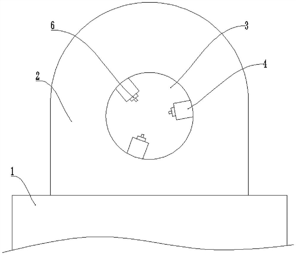
[0033] Basic as attached figure 1 And attached figure 2 Shown: the jointing device for steel pipe rods, including workbench 1, which is provided with a clamping mechanism for the steel pipe reel and a welding torch for seaming the gap of the steel pipe reel; the clamping mechanism includes The vertical plate 2 on the platform 1 and the circular hole 3 provided on the vertical plate 2, the inner wall of the circular hole 3 is equidistantly provided with three clamping parts for clamping the steel pipe reel.

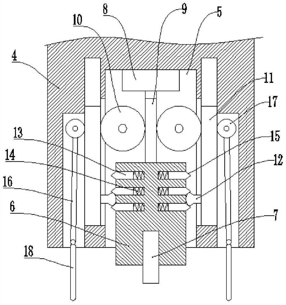
[0034] The clamping part includes a fixed block 4 and a clamping block, the fixed block 4 is fixed on the inner wall of the round hole 3, and the middle part of the fixed block 4 is vertically opened with a groove 5; the clamping block includes a lifting block 6 and a round wheel 7 , Lifting block 6 is vertically provided with storage tank, and round wheel 7 is affixed with the both sides inner wall of storage tank, and round wheel 7 stretches out storage tank, and the p...

Embodiment 2

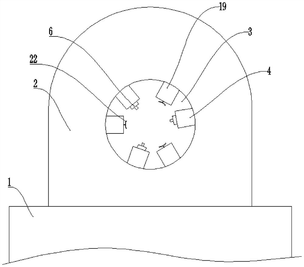
[0046] Basic as attached image 3 And attached Figure 4 As shown, the structure and implementation of Embodiment 2 are basically the same as that of Embodiment 1. The difference is that three supporting platforms 19 are fixed on the inner wall of the circular hole 3 in the circumferential direction, and each supporting platform 19 is located at two adjacent Between the fixed blocks 4; the support platform 19 is vertically provided with a vertical groove, and the inwall of the vertical groove is fixedly connected with a second cylinder 20, and the output shaft of the second cylinder 20 is fixedly connected with an auxiliary rod 21, and the auxiliary An arc-shaped plate 22 is fixedly connected to the rod 21, and the arc-shaped plate 22 protrudes from the vertical groove.

[0047] The specific implementation process is as follows:

[0048] Start the second cylinder 20, the output shaft of the second cylinder 20 drives the auxiliary rod 21 to move in the direction of the steel ...


PUM


Abstract

The invention relates to the technical field of bar welding; it discloses a steel pipe rod seam closing device, including a workbench, on which a clamping mechanism for a steel pipe reel and a welding torch for seaming the gap of the steel pipe reel are arranged, and the clamping The mechanism includes a vertical plate fixed on the workbench and a circular hole opened on the vertical plate. The inner wall of the circular hole is provided with at least three retractable clamping parts for clamping the steel pipe reel at an equidistant distance on the inner wall of the circular hole. . This scheme mainly solves the problem that the joint effect is affected due to poor positioning effect when the steel pipe reel is jointed.

Description

technical field [0001] The invention relates to the technical field of bar welding. Background technique [0002] Most of the large-diameter steel pipe rods are made of single steel plates, which need to be welded after forming a cylinder. Specifically, there will be gaps reserved for steel pipe reels, and the gaps between the steel pipe reels need to be jointed. [0003] At present, before the welding process, it is necessary to place the steel pipe reel on the workbench, and then directly press and position it with the hands of the staff, or the staff hold the plate to press the position tightly, and then close the gap between the steel pipe reel In the actual operation process, the positioning effect of the steel pipe reel by direct pressing with the hand and the tightness of the plate is not good, resulting in the shaking of the steel pipe reel in the gap, so that there is a height difference in the gap of the steel pipe reel, directly Affect the joint effect of the ste...

Claims


Application Information

Patent Timeline
Patent Type & Authority Patents(China)
IPC IPC(8): B23K37/053B23K31/02
CPCB23K31/02B23K37/053
Inventor 赵长刚
Owner 重庆市荣昌区永世光电设备有限公司
Why Eureka
Try Eureka