

Method for positioning and assembling composite material rotor blade of C-shaped beam structure
A composite material and rotor blade technology, which is applied to other household appliances, household appliances, household components, etc., can solve the problems of reducing the service life of the girders, the flight safety of the composite rotor blades, the folds of the girders, and the difficulty of forming a fixed shape. , to achieve the effect of improving product assembly efficiency, improving product qualification rate, and accurate and rapid assembly
- Summary
- Abstract
- Description
- Claims
- Application Information
AI Technical Summary
Problems solved by technology
Method used
Image

Examples
Embodiment Construction
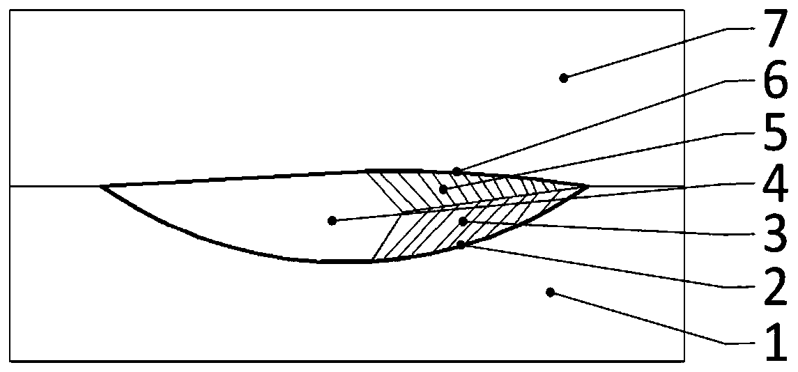
[0022] The object of the present invention is to provide a kind of new C-shaped beam structure composite material rotor blade positioning assembly method, comprising the following steps:
[0023] 1. Complete the paving of the lower mold skin 2 and the upper mold skin 6 on the lower die 1 and the upper die 7 respectively;
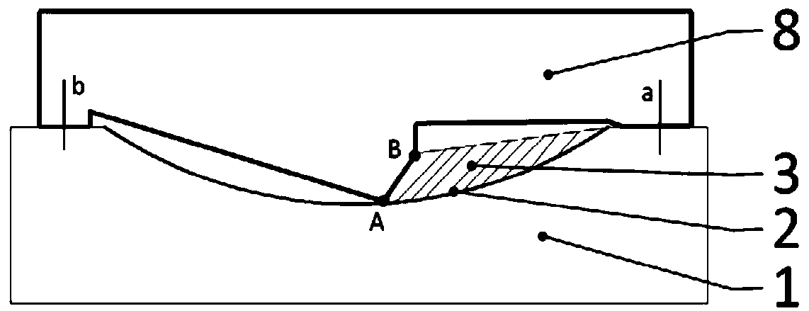
[0024] 2. First install the lower mold girder 3 on the lower mold skin, and use the chord-wise section shape template 8 to perform positioning calibration on the lower mold girder 3 to ensure that the placement position and direction of the girder are accurate;
[0025] 3. After installing the paddle foam core 4 on the lower mold beam 3, install the upper mold beam 5;
[0026] 4. Use tools such as rolling board to comb and compact the composite material girder;
[0027] 5. Clamp the upper and lower dies with the paved skin, and heat and pressurize to cure.
[0028] Further, the outline of the two-point area A and B of the chordwise section outline template...
PUM
 Abstract
Description
Claims
Application Information