
Liquid flow type pressurization device

A pressurization device and flow-type technology, which is applied in the direction of liquid fuel engines, pump devices, and components of pumping devices for elastic fluids, can solve problems such as poor control ability and insufficient pressure, and achieve the effect of improving work efficiency

Active Publication Date: 2020-06-02
苏州德尔得机电设备有限公司
View PDF5 Cites 5 Cited by
  • Summary
  • Abstract
  • Description
  • Claims
  • Application Information

AI Technical Summary

Problems solved by technology

[0002] At present, in many places, there is a problem of insufficient pressure when the liquid is flowing, and the existing method is to use a turbine to pressurize the support, resulting in many limitations in the pressurization, and the control ability is relatively poor

Method used


Image

  • Liquid flow type pressurization device
  • Liquid flow type pressurization device
  • Liquid flow type pressurization device

Examples


Embodiment Construction

[0020] The following will clearly and completely describe the technical solutions in the embodiments of the present invention with reference to the accompanying drawings in the embodiments of the present invention. Obviously, the described embodiments are only some, not all, embodiments of the present invention. Based on the embodiments of the present invention, all other embodiments obtained by persons of ordinary skill in the art without making creative efforts belong to the protection scope of the present invention.

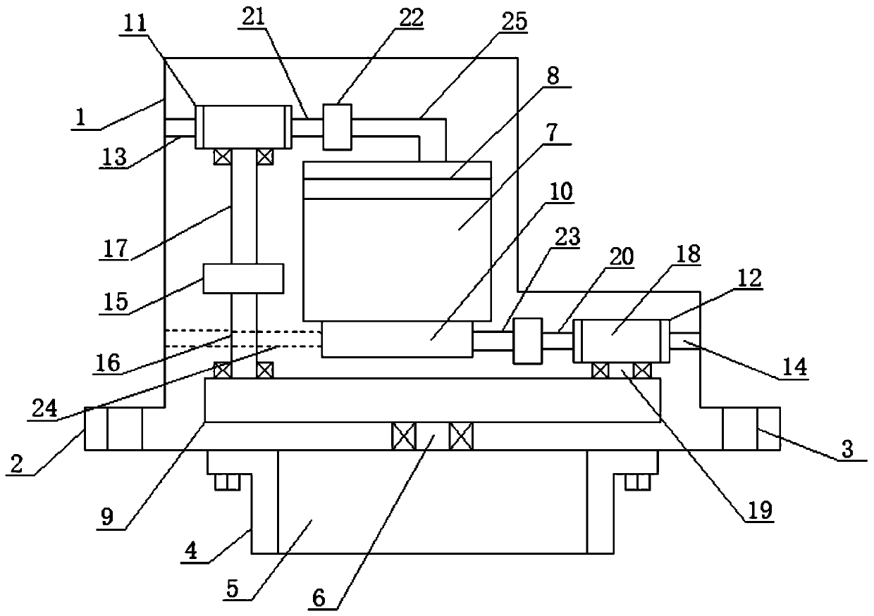
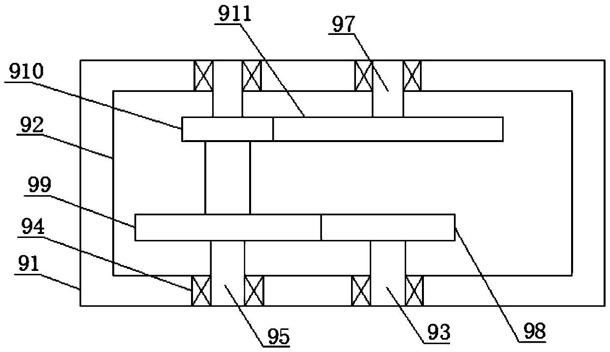
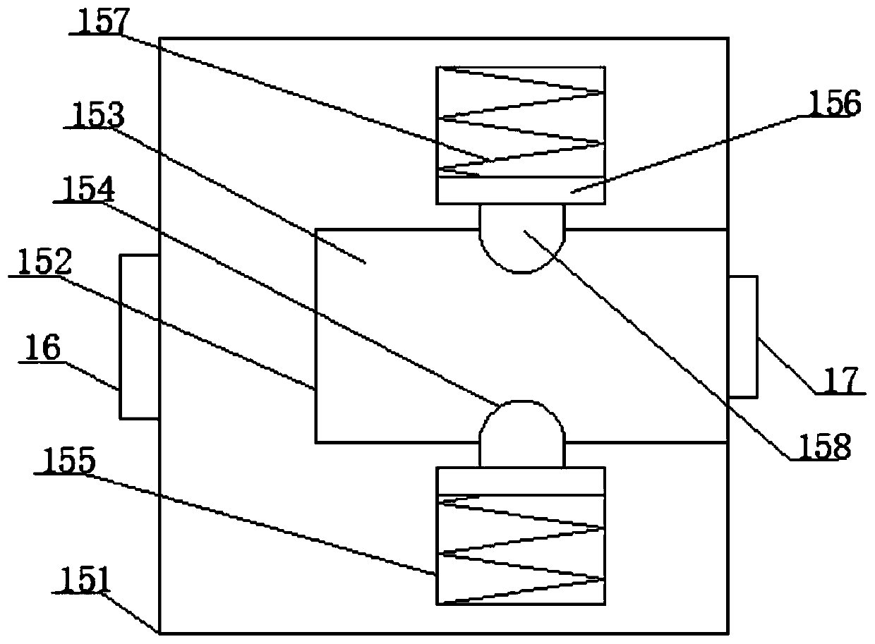
[0021] see figure 1 , an embodiment provided by the present invention: includes a main body shell 1, the bottom of the side of the main body shell 1 is provided with a main connecting plate structure 2 integrated with it, and the inside of the main connecting plate structure 2 is provided with a main Bolt holes 3, a drive motor installation shell 4 is installed at the bottom center of the main body shell 1, and a gear set meshing rotation speed enhancement mec...


PUM


Abstract

The invention discloses a liquid flow type pressurization device. The liquid flow type pressurization device comprises a main body shell. By using a driving motor, a driving function of liquid duringinjection can be achieved, a pressure auxiliary function is formed when the air enters, and two variables are determined, so that the energy when the liquid is discharged is controllable, and the pressurization can be carried out under the premise of the continuous flow of water. Moreover, the device is provided with a gear set meshing rotary speed enhancement mechanism and the rotation speed of the driving motor can be strengthened, so that the working efficiency is improved. Moreover, the device is provided with a circular array spiral spring abutting rotation resistance control mechanism, and the strength of a spiral spring is used for controlling the air pressure value. In addition, the device is provided with a large pressure sphere type air-liquid one-way flow mechanism, and the large pressure sphere type air-liquid one-way flow mechanism can control the one-way flow of gas-liquid liquid.

Description

technical field [0001] The invention relates to the technical field of water flow drive, in particular to a liquid flow type booster device. Background technique [0002] At present, in many places, there is a problem of insufficient pressure when the liquid is flowing, and the existing method is to use a turbine to pressurize the support, which has many limitations in the pressurization, and the control ability is relatively poor. Contents of the invention [0003] The purpose of the present invention is to provide a liquid flow type pressurization device to solve the problems raised in the background art above. [0004] In order to achieve the above object, the present invention provides the following technical solution: a liquid flow type supercharging device, including a main body shell, the bottom of the side of the main body shell is provided with a main connecting plate structure integrated with it, and the main connecting plate structure The inside of the plate st...

Claims


Application Information

Patent Timeline
Patent Type & Authority Applications(China)
IPC IPC(8): F04D13/06F04D29/00F04D15/00
CPCF04D13/06F04D15/00F04D29/007
Inventor 胡晓勇
Owner 苏州德尔得机电设备有限公司
Learn More