[0025] In order to make the objectives, technical solutions, and advantages of the embodiments of the present invention clearer, the technical solutions of the embodiments of the present invention will be described clearly and completely in conjunction with the accompanying drawings of the embodiments of the present invention. Obviously, the described embodiments are part of the embodiments of the present invention, rather than all of the embodiments.
[0026] Based on the described embodiments of the present invention, all other embodiments obtained by a person of ordinary skill in the art without creative work shall fall within the protection scope of the present invention. Unless otherwise defined, the technical terms or scientific terms used in the present disclosure shall have the ordinary meanings understood by those with ordinary skills in the field to which the present invention belongs.
[0027] The "first", "second" and similar words used in the present disclosure do not indicate any order, quantity, or importance, but are only used to distinguish different components. Similarly, similar words such as "a", "one" or "the" do not mean a quantity limit, but mean that there is at least one. "Include" or "include" and other similar words mean that the element or item appearing before the word encompasses the element or item listed after the word and its equivalents, but does not exclude other elements or items. Similar words such as "connected" or "connected" are not limited to physical or mechanical connections, but may include electrical connections, whether direct or indirect. "Up", "Down", "Left", "Right", etc. are only used to indicate the relative position relationship. When the absolute position of the described object changes, the relative position relationship may also change accordingly.
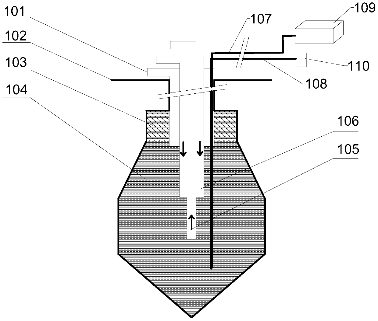
[0028] The fitness gas storage is formed by artificially dissolving the cavity in a suitable stratum. In the process of dissolving the cavity, the halogen is generally dissolved by hot water 104 to form a cavity. In this process, in order to avoid upward dissolution, the hot water 104 An oil seal is required on the upper surface, and knowing the interface between diesel fuel 103 and water 104 is beneficial to save oil consumption.
[0029] The present invention provides a liquid interface sensing detection method, which is suitable for detecting the position of the interface in the depth direction of two or more liquids in the same cavity, and the method includes the following contents:
[0030] The temperature change part operates the same heating source to act on the liquid in the cavity to change the temperature; the detection part continuously detects when the temperature of the liquid changes to obtain multiple different depth positions of the liquid in a specific time period Analyze the positioning part, analyze and process the dynamic temperature information obtained to know the different positions of the liquid temperature change law, so as to locate the interface of each liquid.
[0031] Taking the dissolved cavity of a gas storage as an example, the diesel 103 and water 104 in the dissolved cavity are heated by a heating source, and after heating to a preset temperature, the heating source is stopped to make the temperature of the oil and water 104 fall back to normal temperature. In this process, the temperature dynamic information of a number of different depth positions is detected. Through analysis and processing, a heating curve or a cooling curve can be formed that can show the law of liquid temperature change. Because the specific heat capacities of oil and water 104 are different, the difference between the two There will be differences between the heating curve and the cooling curve, and the position where the difference occurs corresponds to the interface between oil and water 104.
[0032] Specifically, when the law of temperature change is known, only the dynamic temperature information within a certain period of time can be used. For example, the temperature data during the period of time when the oil and water 104 are heated to a preset value and then fall back to normal temperature is analyzed and processed. Then, different cooling curves are obtained, and the difference between the cooling curves corresponds to the 104 interface of oil and water.
[0033] For the continuous detection and acquisition of dynamic temperature information at different depths of the liquid within a certain period of time, distributed optical fiber temperature measurement technology can be used to achieve. Distributed optical fiber temperature measurement technology (DTS) is also known as Optical fiber temperature measurement According to the principle of optical time domain reflection and the sensitivity of Raman scattering to temperature, temperature monitoring can be realized, and temperature information corresponding to different depth positions can be obtained continuously and in real time.
[0034] The present invention provides a liquid interface sensing detection device capable of realizing the aforementioned method. The device is suitable for detecting the position of the interface in the depth direction of two or more liquids in the same cavity, and includes:
[0035] The heating component has a certain length to extend into the cavity to heat the liquid;
[0036] A temperature control component connected to the heating component;
[0037] A temperature detection component, which includes an information detection carrier and a host part, the information detection carrier has a certain length to extend into the cavity (in liquid), and the host part learns that the heating component is affected by the information detection carrier The dynamic temperature information of the corresponding depth position of the liquid and transmitted;
[0038] An industrial control device is connected with the temperature control component to send operation instructions of the heating component; connected with the temperature detection component, and receives and processes the dynamic temperature information to identify and locate the liquid interface according to different positions of the temperature change law.
[0039] Specifically, the heating component uses a heating cable 108, the temperature control component is a temperature control meter 110, and the temperature control meter 110 is connected to the heating cable 108; and for continuous and regular detection of different depth positions of the liquid, a distributed optical fiber temperature measuring device can be used To achieve this, the information detection carrier includes armored optical cable 107 (the optical cable is covered with a protective "armor" to protect the inner core, and has the functions of resistance to strong pressure, tension, and high temperature). The armored optical cable 107 can continuously monitor The monitoring accuracy of the sensing components can be selected according to specific needs, such as 1 meter or 0.5 meters, etc. The host part includes a distributed optical fiber temperature measurement host 109 connected to the end of the armored optical cable 107, a temperature control meter 110 and a distributed The control end of the optical fiber temperature measurement host 109 is connected to an industrial computer (ie, an industrial control device). The industrial computer is equipped with a MATLAB system, which can process data to obtain the temperature change law of oil and water 104, which is generally identified by a heating curve and a cooling curve. Therefore, the interface of oil and water 104 in the dissolved cavity of the gas storage is determined.
[0040] See attached figure 1 , Configure a high-precision distributed optical fiber temperature measurement device for the gas storage. The armored optical cable 107 connected to the distributed optical fiber temperature measurement host 109 and the heating cable 108 connected to the temperature control meter 110 extend from the ground 102 through the diesel pipeline 101 Into the bottom of the gas storage.
[0041] After everything is ready, turn on the high-precision distributed optical fiber temperature measurement host 109, ready to start measuring the temperature at different depths and recording data. Water 104 is injected into the interlayer water pipeline 106, and a certain amount of diesel 103 is injected into the diesel 103 pipeline. When the water 104 is injected to a certain amount, the brine 104 starts to spray out from the inner water pipe 105. This is the cavity effect. Without a distributed optical fiber temperature measuring device, it is impossible to know where the interface between oil and water 104 is. At this time, the temperature control meter 110 is energized by the industrial computer sending instructions, the heating cable 108 starts to work, and the liquid in the gas storage starts to be heated. Because the oil and water 104 have different specific heat capacities and different thermal conductivity, so the two will not be different The law of temperature changes. When the temperature rises to a certain value, the power of the temperature control meter 110 is cut off, the temperature in the gas storage begins to drop, and the temperature of the oil and water 104 is slowly cooled to normal temperature.
[0042] In the foregoing process, the distributed optical fiber temperature measurement host 109 obtains the oil and water 104 dynamic temperature data at the corresponding depth position in the corresponding time period through the armored optical cable 107, and the temperature data corresponding to the corresponding depth position passes through the host's Ethernet The interface is uploaded to the industrial computer, and the data is processed by MATLAB to obtain the heating curve and cooling curve of oil and water 104. Due to the difference in specific heat capacity, the temperature change curve of oil and water 104 will be very different. This difference The resulting position is the oil-water 104 interface.
[0043] When the armored optical cable 107 and the heating cable 108 are put into the gas storage, the parallel layout of the two will help to save energy, that is, the parts of the two that extend into the gas storage can be bound in parallel, and the armored optical cable The distance between 107 and the heating cable 108 can be detected more quickly, and the temperature change of the liquid near the heating cable 108 can be detected more quickly. This avoids the need for a large area of the heating cable 108 to heat a large amount of oil and water 104 for a long time. Energy waste. Generally, after the temperature rises to a certain predetermined temperature, the heating cable 108 can be stopped to detect and analyze the cooling process, and the position of the oil-water 104 interface can be determined according to the different positions of the cooling curve.
[0044] The method and device for detecting oil and moisture interface of gas storage provided by the present invention have the characteristics of high resolution, high speed sampling rate, high accuracy, etc., and relevant data can be obtained without manual intervention, which not only saves labor costs, but also reduces the melting cavity cost.
[0045] The above descriptions are only preferred embodiments of the present invention and are not used to limit the present invention. For those skilled in the art, the present invention can have various modifications, combinations and changes. Any modification, equivalent replacement, improvement, etc., made within the spirit and principle of the present invention should be included in the scope of the claims of the present invention.