Equipment fault identification system

A technology for equipment failure and recognition systems, applied in character and pattern recognition, pattern recognition in signals, measuring devices, etc., can solve problems such as reducing efficiency, affecting maintenance personnel's elevator maintenance work, wasting time, etc.

Active Publication Date: 2020-06-02
MOCHITEC SHANGHAI CO LTD
View PDF7 Cites 6 Cited by
  • Summary
  • Abstract
  • Description
  • Claims
  • Application Information

AI Technical Summary

Problems solved by technology

With the rapid increase in the number of elevators in recent years, the number of maintenance personnel has remained the same or even decreased. It has become more and more difficult to ensure timely elevator maintenance and maintenance. Moreover, the elevator structure is complex, and when a problem occurs, it cannot be accurately located, and a large number of investigations will be required It wastes time, reduces efficiency, and will also affect the subsequent elevator maintenance work of maintenance personnel
[0004] In reality, elevator failures are often found only when passengers are trapped, resulting in property losses and casualties caused by untimely discovery and rescue. There are even more hasty maintenance personnel who fail to solve core problems or even discover potential hidden dangers. It leads to other faults, ranging from mild to severe. Therefore, it is more important to develop a system that can independently identify and judge elevator faults. After machine identification, maintenance personnel can directly prescribe the right medicine, and at the same time accumulate maintenance experience for maintenance personnel , reduce maintenance time consumption, eliminate potential hidden dangers, and improve elevator safety and user experience in a timely manner

Method used


Image

  • Equipment fault identification system
  • Equipment fault identification system
  • Equipment fault identification system

Examples


Embodiment Construction

[0066] Preferred embodiments of the present invention will be described in detail below in conjunction with the accompanying drawings.

[0067] In order to further understand the present invention, the preferred embodiments of the present invention are described below in conjunction with examples, but it should be understood that these descriptions are only to further illustrate the features and advantages of the present invention, rather than limiting the claims of the present invention.

[0068] The description in this part is only for several typical embodiments, and the present invention is not limited to the scope of the description of the embodiments. The mutual replacement of the same or similar prior art means and some technical features in the embodiments is also within the scope of the description and protection of the present invention.

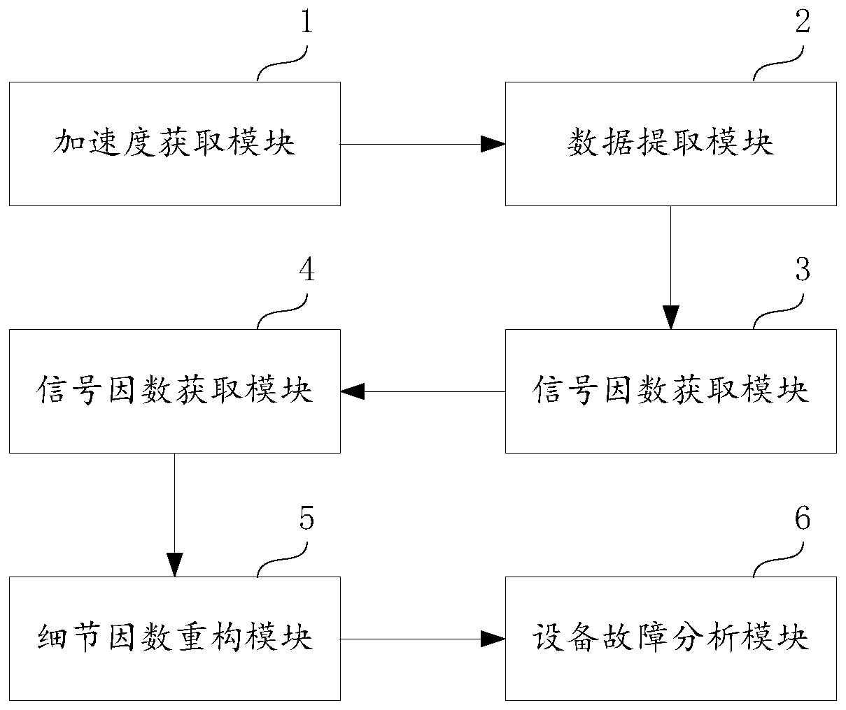
[0069] The invention discloses an equipment fault identification system, figure 1 It is a schematic diagram of the composition o...


PUM


Abstract

The invention discloses an equipment fault identification system. The equipment fault identification system comprises an acceleration acquisition module, a data extraction module, a wavelet transformation module, a detail factor reconstruction module, an equipment state identification module, an equipment fault analysis module and a fault model module. The acceleration acquisition module acquiresacceleration data in a set direction in the operation process of a set component of the equipment; the data extraction module acquires acceleration data acquired by the acceleration acquisition module; the wavelet transformation module transforms the complete signal of the equipment moving once to obtain a detail factor of the signal; the detail factor reconstruction module is used for reconstructing detail factors; the equipment state identification module identifies the state of the equipment according to the characteristics of the reconstructed acceleration data; and the equipment fault analysis module is used for judging whether the equipment has faults or not according to the equipment state fed back by the equipment state identification module. According to the system, the equipmentstate can be obtained in real time, and the equipment problem is determined according to related characteristics.

Description

technical field [0001] The invention belongs to the technical field of equipment fault detection, and relates to an equipment fault identification system. Background technique [0002] According to national statistics, based on the analysis of demand in traditional real estate, rail transit, upgrading and other fields, it is expected that domestic elevator sales will continue to increase in 2020. From 2013 to 2017, the number of domestic elevators has soared from 3 million to nearly 6 million. At the same time, the completed area of ​​domestic real estate is also steadily increasing. [0003] While the number and development prospects of domestic elevators are soaring, elevators lack effective technical means for safety supervision, and only rely on maintenance personnel for regular inspection and maintenance. There is also an article in the 21st issue of China Equipment Engineering in 2019 "The status quo of elevator maintenance Discussion on the Direction and Direction po...

Claims


Application Information

Patent Timeline
Patent Type & Authority Applications(China)
IPC IPC(8): G06K9/00G01H17/00
CPCG01H17/00G06F2218/02G06F2218/08
Inventor 欧阳世童马琪聪李金鹏齐洋
Owner MOCHITEC SHANGHAI CO LTD
Why Eureka
Try Eureka