Contactless switch

A contact-free and switching technology, which is applied in the direction of electronic switches, electrical components, pulse technology, etc., can solve the problems of low safety and unhealthy direct contact, and achieve the effects of long durability, avoiding cross-infection, and simple production

Pending Publication Date: 2020-06-02
姜泽华
View PDF0 Cites 0 Cited by
  • Summary
  • Abstract
  • Description
  • Claims
  • Application Information

AI Technical Summary

Problems solved by technology

[0003] The invention provides a non-contact switch to solve the problems of unhealthy and low safety of direct contact existing in the prior art

Method used


Image

  • Contactless switch
  • Contactless switch
  • Contactless switch

Examples


example 2

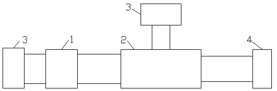
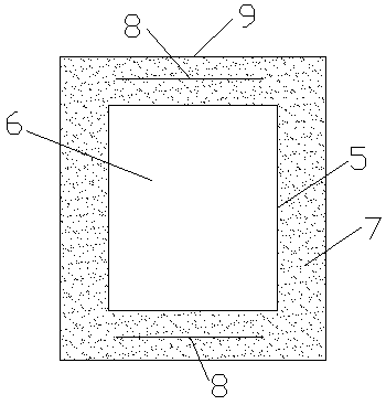
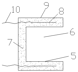
[0028] Such as figure 1 , figure 2 , image 3 , Figure 7 , Figure 8 and Figure 9As shown, a non-contact switch is composed of a signal generator 1, an auxiliary circuit 2 and a working power supply 3. The signal generator 1 is connected to the auxiliary circuit 2 through a wire 10. The auxiliary circuit 2 is equipped with a switch circuit. The signal generator 1 is composed of The metal cylinder 5, the insulating hard material layer 7, the electric signal generating mechanism 8 and the metal film 9 are composed of a cavity 6 inside the metal cylinder 5, the insulating hard material layer 7 is arranged on the outer surface of the metal cylinder 5, and the metal film 9 is coated on the outer surface of the insulating hard material layer 7, the electrical signal generating mechanism 8 is embedded in the insulating hard material layer 7, the insulating hard material layer 7 is used as a supporting member of the electrical signal generating mechanism, and the electrical sig...

example 3

[0030] Such as figure 1 , figure 2 , image 3 , Figure 10 , Figure 11 and Figure 12 As shown, a non-contact switch is composed of a signal generator 1, an auxiliary circuit 2 and a working power supply 3. The signal generator 1 is connected to the auxiliary circuit 2 through a wire 10. The auxiliary circuit 2 is equipped with a switch circuit. The signal generator 1 is composed of The metal cylinder 5, the insulating hard material layer 7, the electric signal generating mechanism 8 and the metal film 9 are composed of a cavity 6 inside the metal cylinder 5, the insulating hard material layer 7 is arranged on the outer surface of the metal cylinder 5, and the metal film 9 is coated on the outer surface of the insulating hard material layer 7, the electrical signal generating mechanism 8 is embedded in the insulating hard material layer 7, the insulating hard material layer 7 is used as a supporting member of the electrical signal generating mechanism, and the electrical...


PUM


Abstract

A contactless switch comprises a signal generator, an auxiliary circuit and a working power supply, wherein the signal generator is connected with the auxiliary circuit through a wire; a switching circuit is arranged in auxiliary circuit; the signal generator is composed of a metal cylinder, an insulating hard material layer, an electric signal generating mechanism and a metal film; a cavity is formed in the metal cylinder; the metal film wraps the outer surface of the insulating hard material layer; the electric signal generating mechanism is embedded into the insulating hard material layer;the insulating hard material layer serves as a supporting component of the electric signal generating mechanism; and a wire is led out of the electric signal generating mechanism to the auxiliary circuit. The switch does not need to be touched by hands such that cross infection is avoided; no physical electric contact point exists, the circuit operation is stable, and the durable time is long; manufacturing cost is low, and manufacturing is simple; the original circuit design is not changed, and various switches and keys which can be instantly switched on and off by hand contact or hand pressing can be widely replaced.

Description

technical field [0001] The invention relates to the technical field of power switches, in particular to a contactless switch. Background technique [0002] Switches are indispensable electrical control components in people's production and life, and most of them need to be touched by people to operate. Switches in public places are frequently used due to the large flow of people, such as touch-delay lighting switches in public buildings, ATM machine buttons, bank password input devices, elevator call buttons and floor selection buttons. In this case, it is very easy to cause the operation contact surface of the switch to be contaminated with bacteria, resulting in cross infection, thus causing great hidden dangers to people's health; in addition, most of the electrical contacts of these switches are physical contacts, which take a long time The electrical contact point will be oxidized and worn to varying degrees, and there is a hidden danger of poor electrical contact, whi...

Claims


Application Information

Patent Timeline
Patent Type & Authority Applications(China)
IPC IPC(8): H03K17/955H03K17/95H03K17/945
CPCH03K17/945H03K17/952H03K17/955
Inventor 姜泽华
Owner 姜泽华
Why Eureka
Try Eureka