
Self-adjusting security camera based on reversible reaction principle

A camera and adjusting security technology, which can be used in photography, image communication, camera body and other directions, and can solve the problems of unclear shooting and poor shading effect.

Active Publication Date: 2020-06-02
浙江沪宁电子科技有限公司
View PDF16 Cites 1 Cited by
  • Summary
  • Abstract
  • Description
  • Claims
  • Application Information

AI Technical Summary

Problems solved by technology

[0005] The purpose of the present invention is to provide a self-adjusting security camera based on the reversible reaction principle that can adjust the shading effect according to the light intensity to solve the problem that the above-mentioned poor shading effect leads to unclear shooting

Method used


Image

  • Self-adjusting security camera based on reversible reaction principle
  • Self-adjusting security camera based on reversible reaction principle
  • Self-adjusting security camera based on reversible reaction principle

Examples


Embodiment 1

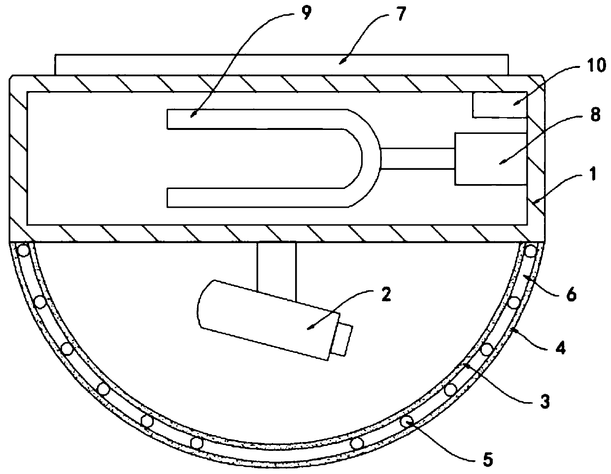
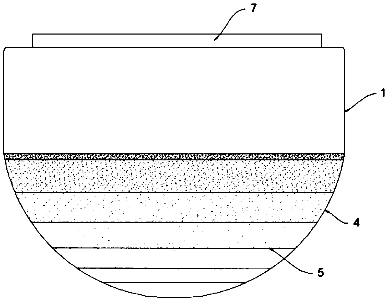
[0018] Such as Figure 1-2 As shown, a self-adjusting security camera based on the reversible reaction principle includes a base 1 fixedly installed on a building, a camera 2 is installed at the lower end of the base 1, and the camera 2 is surrounded by a hemispherical inner transparent cover 3 and The outer transparent cover 4 is set outside the inner transparent cover 3. The inner transparent cover 3 and the outer transparent cover 4 are fixedly connected to the base 1. Conductive rings 5 ​​whose root diameters decrease step by step from top to bottom. The conductive rings 5 ​​are made of indium tin oxide material. Indium tin oxide is conductive and transparent, so as to avoid blocking the camera 2. Multiple conductive rings 5 ​​are arranged horizontally , and the conductive ring 5 forms a closed loop, and the plurality of conductive rings 5 ​​divide the space between the inner transparent cover 3 and the outer transparent cover 4 into a plurality of annular light-transmitti...

Embodiment 2

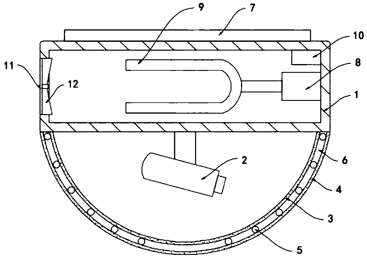
[0022] Such as image 3 As shown, the difference between this embodiment and Embodiment 1 is that the side wall of the base 1 is provided with an air vent 11 communicating with the interior of the base 1, and a fan 12 is rotatably connected to the side wall of the air vent 11. The two fan blades of 12 are all made of magnetic material and have opposite magnetic poles.

[0023] In this embodiment, when the motor 8 drives the U-shaped magnet 9 to rotate, under the action of the magnetic force, it drives the fan 12 to rotate, which speeds up the air flow at the vent 11, improves the heat exchange speed between the inside of the base 1 and the outside, and plays a role in ventilation. cooling effect.


PUM


Abstract

The invention belongs to the field of security monitoring, and in particular relates to a self-adjusting security camera based on a reversible reaction principle. The self-adjusting security camera comprises a base fixedly mounted on a building, a camera is mounted at the lower end of the base; a hemispherical inner transparent cover and a hemispherical outer transparent cover are arranged outsidethe camera in a surrounding mode. The outer transparent cover is arranged outside the inner transparent cover in a sleeving manner; the inner transparent cover and the outer transparent cover are both fixedly connected with the base. A plurality of conducting rings of which the diameters are gradually reduced from top to bottom are fixedly arranged between the inner transparent cover and the outer transparent cover; the conducting rings are made of indium tin oxide materials, the space between the inner transparent cover and the outer transparent cover is divided into a plurality of annular light-transmitting cavities by the conducting rings, and the annular light-transmitting cavities are filled with nitrogen dioxide and nitrogen tetroxide mixed gas. The area of a dark area of the annular light-transmitting cavities from top to bottom can be adjusted according to the illumination intensity, so that background illumination is automatically adapted, the visual field is sacrificed as little as possible, and the definition of an image area is improved.

Description

technical field [0001] The invention belongs to the field of security monitoring, in particular to a self-adjusting security camera based on the principle of reversible reaction. Background technique [0002] Security camera refers to the camera used in security protection. Its main features are high sensitivity, anti-glare, small distortion, small size, long life, shock resistance, and can be monitored by remote control, so it is widely used. [0003] For the current outdoor cameras, it is generally faced with the problem of strong backlight, that is, when the direction facing the lens has a strong background light, the brightness of the captured image is extremely low, and the image processing module can only control the captured image. The overall brightness of the camera is increased, and the adjusted image definition is very limited, even blurred. For this reason, the sun visor is generally installed above the lens of the outdoor camera. When the sun visor is small, th...

Claims


Application Information

Patent Timeline
IPC IPC(8): H04N5/225G03B15/02G03B15/06G03B17/55H04N7/18
CPCG03B15/02G03B15/06G03B17/55H04N7/18H04N23/52H04N23/50H04N23/51
Inventor 李媛孙瑜格
Owner 浙江沪宁电子科技有限公司
Learn More