
Method for calculating workpiece surface roughness during cylindrical turning by considering workpiece vibration

A technology for workpiece surface and external turning, which is used in metal processing machinery parts, manufacturing tools, metal processing equipment, etc., and can solve the problems of complicated measurement and calculation, increase of workpiece surface roughness, and difficulty in predicting and calculating workpiece surface roughness. Achieve the effect of high precision, simple calculation method and improved surface quality

Active Publication Date: 2020-06-05
SHANDONG UNIV OF TECH
View PDF6 Cites 0 Cited by
  • Summary
  • Abstract
  • Description
  • Claims
  • Application Information

AI Technical Summary

Problems solved by technology

However, this model needs to measure the tool vibration acceleration signal online during turning, the measurement and calculation are relatively complicated, and it is difficult to predict and calculate the surface roughness of the workpiece before turning
[0004] In the external turning process, the relative vibration between the machine tool, the tool and the workpiece will cause the tool to leave uneven marks on the surface of the workpiece, resulting in an increase in the surface roughness of the workpiece
This vibration signal is unavoidable, and it is difficult to measure it accurately during processing due to the influence of many factors

Method used


Image

  • Method for calculating workpiece surface roughness during cylindrical turning by considering workpiece vibration
  • Method for calculating workpiece surface roughness during cylindrical turning by considering workpiece vibration
  • Method for calculating workpiece surface roughness during cylindrical turning by considering workpiece vibration

Examples


Embodiment Construction

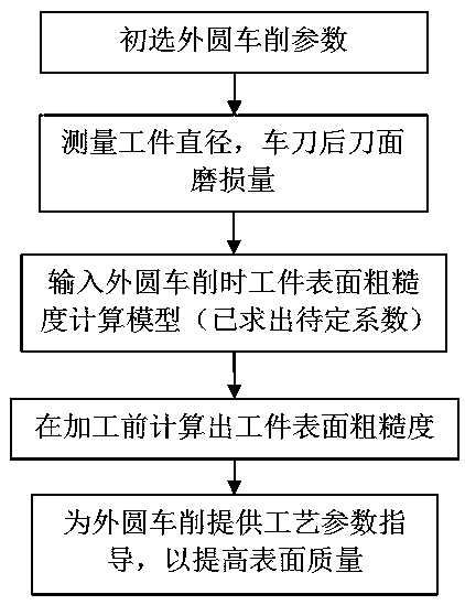
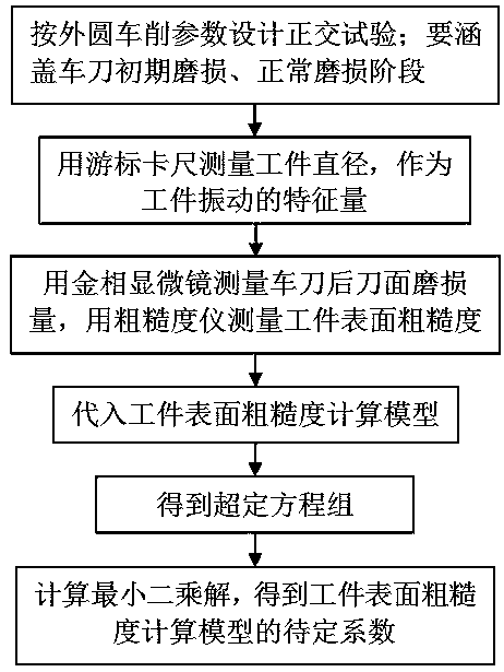
[0018] Combine below figure 1 figure 2 The present invention is further described in detail.

[0019] In step 1), according to the machine tool-tool-workpiece vibration theory, the impact of the vibration of the workpiece in the direction of cutting depth on the roughness is much greater than the vibration in other directions. For the cylindrical turning of shaft parts, the diameter of the workpiece is taken as a characteristic quantity of the workpiece vibration, and the calculation model of the surface roughness of the workpiece is established based on the turning parameters, workpiece diameter, and tool wear:

[0020] R a =k×a p a × f b ×V c ×D d ×VB e (1)

[0021] Among them, R a is the surface roughness of the workpiece; a p is the amount of back cutting; f is the feed; V is the cutting speed; D is the diameter of the workpiece; VB is the amount of wear on the flank of the turning tool;

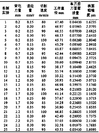
[0022] In step 2), with the help of vernier calipers, roughness meter,...


PUM

PropertyMeasurementUnit
surface roughnessaaaaaaaaaa

Abstract

The invention provides a method for calculating workpiece surface roughness during cylindrical turning by considering workpiece vibration. The method includes the following steps of firstly, establishing a model for calculating the workpiece surface roughness during cylindrical turning according to a machine tool-tool-workpiece vibration theory on the basis of turning parameters, a workpiece diameter and tool abrasion; secondly, measuring and calculating all undetermined coefficients in the model for calculating the workpiece surface roughness during cylindrical turning with the aid of a vernier caliper, a roughmeter and a metalloscope; and thirdly, calculating the workpiece surface roughness during cylindrical turning before machining for a ground of new technological parameters accordingto the turning parameters, the workpiece diameter and the tool abrasion loss under the conditions of the same machine tool, the same clamping mode, the same tool material, the same workpiece materialand the same machining mode. The method has the advantages that the workpiece diameter serves as a characteristic quantity of workpiece vibration during cylindrical turning, the workpiece surface roughness is calculated by comprehensively considering the influences of the turning parameters, the workpiece vibration and the tool abrasion, and the calculating method is simple and high in precision.

Description

technical field [0001] The invention relates to a method for calculating the surface roughness of a workpiece, in particular to a method for calculating the surface roughness of a workpiece during outer circle turning considering the vibration of the workpiece. Background technique [0002] For external turning, the surface quality determines the performance of the workpiece. Surface roughness has an important influence on the working accuracy, fit properties and fatigue strength of the workpiece. Generally speaking, the surface roughness is small, which is conducive to improving the quality of fit, reducing wear and prolonging the service life of the workpiece. Technicians hope to know the surface roughness of the processed workpiece in time before the external turning process, so as to make corresponding changes in process parameters, and the ultimate goal is to improve the quality of the workpiece and improve production efficiency. [0003] Many scholars have studied ho...

Claims


Application Information

Patent Timeline
Patent Type & Authority Applications(China)
IPC IPC(8): B23B1/00B23Q17/09B23Q17/20
CPCB23B1/00B23Q17/0904B23Q17/20
Inventor 赵国勇李春霄孟建兵周海安李学伟
Owner SHANDONG UNIV OF TECH
Learn More