Numerical control horizontal lathe equipment

A horizontal lathe and equipment technology, applied in turning equipment, turning equipment, metal processing equipment, etc., can solve the problems of speeding up loosening, increasing the friction between the nut and the screw, increasing the weight of the nut, etc. The effect of prolonging the service life

Active Publication Date: 2020-06-05
嘉兴市中法天线实业有限公司 +1
View PDF4 Cites 1 Cited by
  • Summary
  • Abstract
  • Description
  • Claims
  • Application Information

AI Technical Summary

Problems solved by technology

[0003] The current CNC horizontal lathe equipment moves the feed system of the tool holder through the screw drive during work. Due to the weight of the feed system of the tool holder, the weight of the nut will be increased during the movement, thereby increasing the distance between the nut and the screw. Friction, to speed up the loosening between the two

Method used


Image

  • Numerical control horizontal lathe equipment
  • Numerical control horizontal lathe equipment
  • Numerical control horizontal lathe equipment

Examples


Embodiment 1

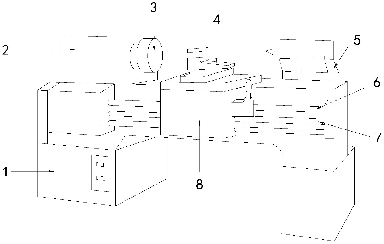
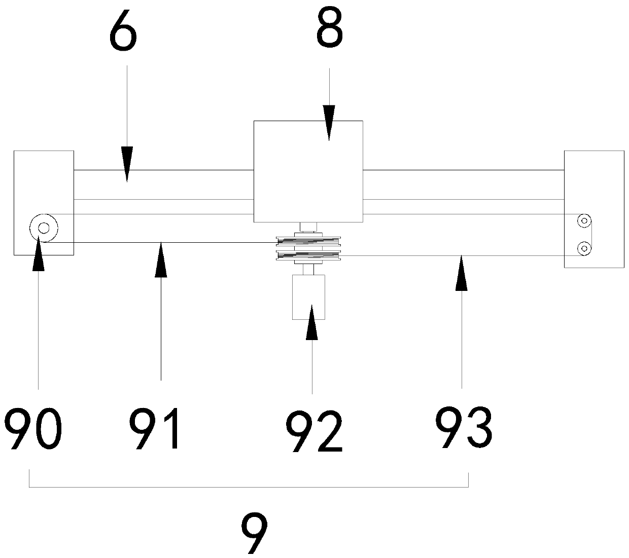
[0027] see Figure 1-3 , the present invention provides a technical solution for CNC horizontal lathe equipment: its structure includes a bed 1, a power box 2, a spindle 3, a tool rest 4, a tailstock 5, a lead screw 6, a feed rod 7, and a tool rest feed system 8 , booster device 9, lead screw 6, feed rod 7 are installed on described bed 1, described tool rest feed system 8 is connected with lead screw 6, feed rod 7 movably, described tool rest feed system 8 tops are arranged There is a tool rest 4, the main shaft 3 is located on the left side of the tool rest 4 and is connected with the power box 2, the power box 2 is fixed on the bed 1, and the right side of the bed 1 is provided with a tailstock 5, so The booster device 9 is connected with the tool post feeding system 8 and is arranged inside the bed 1. The booster device 9 includes a pulley 90, a first stay cord 91, a winding structure 92, and a second stay cord 93. The two sides of the roll structure 92 are respectively c...

Embodiment 2

[0030] see Figure 1-4, the present invention provides a technical solution for CNC horizontal lathe equipment: its structure includes a bed 1, a power box 2, a spindle 3, a tool rest 4, a tailstock 5, a lead screw 6, a feed rod 7, and a tool rest feed system 8 , booster device 9, lead screw 6, feed rod 7 are installed on described bed 1, described tool rest feed system 8 is connected with lead screw 6, feed rod 7 movably, described tool rest feed system 8 tops are arranged There is a tool rest 4, the main shaft 3 is located on the left side of the tool rest 4 and is connected with the power box 2, the power box 2 is fixed on the bed 1, and the right side of the bed 1 is provided with a tailstock 5, so The booster device 9 is connected with the tool post feeding system 8 and is arranged inside the bed 1. The booster device 9 includes a pulley 90, a first stay cord 91, a winding structure 92, and a second stay cord 93. The two sides of the roll structure 92 are respectively co...


PUM


Abstract

The invention discloses numerical control horizontal lathe equipment. The numerical control horizontal lathe equipment structurally comprises a lathe bed, a power box, a main shaft, a tool rest, a tailstock, a lead screw, a polish rod, a tool rest feeding system and a power assisting device, wherein the lead screw and the polish rod are installed on the lathe bed, the tool rest feeding system is movably connected with the lead screw and the polish rod, the tool rest is arranged on the top of the tool rest feeding system, the main shaft is arranged on the left side of the tool rest and is connected with the power box, the power box is fixed on the lathe bed, the tailstock is arranged on the right side of the lathe bed, the power assisting device is connected with the tool rest feeding system and arranged inside the lathe bed, and the power assisting device comprises a pulley, a first pull rope, a winding structure and a second pull rope. The numerical control horizontal lathe equipmenthas the beneficial effects that the moving tool rest feeding system can be assisted by the power assisting device, so that the resistance is reduced, in addition, friction between a nut and the lead screw is reduced, the service life of the nut and the lead screw is prolonged, two movable claws opposite in direction match with a first winding wheel and a second winding wheel so that respective work can be carried out when the two movable claws move in the left direction and the right direction, and mutual interference is avoided.

Description

technical field [0001] The invention relates to the field of numerical control equipment, in particular to a numerical control horizontal lathe equipment. Background technique [0002] CNC lathes, also known as CNC lathes, or computer numerical control lathes, are currently the most widely used and widely covered CNC machine tools in China, accounting for about 25% of the total number of CNC machine tools. It is a mechatronic product integrated with multiple technologies such as microelectronics, information, etc. It is a workhorse with the advantages of high precision, high efficiency, high automation and high flexibility in mechanical manufacturing equipment. [0003] The current CNC horizontal lathe equipment moves the feed system of the tool holder through the screw drive during work. Due to the weight of the feed system of the tool holder, the weight of the nut will be increased during the movement, thereby increasing the distance between the nut and the screw. Frictio...

Claims


Application Information

Patent Timeline
Patent Type & Authority Applications(China)
IPC IPC(8): B23B7/00B23Q5/40B23Q5/34
CPCB23B7/00B23Q5/34B23Q5/40
Inventor 王运来
Owner 嘉兴市中法天线实业有限公司
Why Eureka
Try Eureka