A cooling water spray component for laser cutting, a spray device and a laser cutting machine

A laser cutting machine and laser cutting technology, applied in laser welding equipment, metal processing equipment, welding equipment, etc., can solve the problems of hot nozzle of the cutting head, cooling of the plate that cannot be cut, and cooling of the nozzle of the laser cutting head. , to achieve the effect of improving the effect, preventing excessive heating, and increasing the space

Active Publication Date: 2021-12-24
株洲特装智能装备有限公司
View PDF9 Cites 2 Cited by
  • Summary
  • Abstract
  • Description
  • Claims
  • Application Information

AI Technical Summary

Problems solved by technology

[0002] Due to the high power and oxygen assistance in the process of cutting thick carbon steel, high-power laser cutting will cause the nozzle of the cutting head to become hot, and the overheating of the plate will affect the quality and stability of the cutting effect; especially the new cutting process Small hole nozzles and full high-power laser cutting can get good processing results, but the nozzles of the cutting head are the easiest to get hot. As long as the nozzles are hot, good processing quality cannot be achieved, and the stability is also poor.
[0003] Currently CN208743919U discloses a laser cutting head water cooling protection device, which is arranged on the sensor of the laser cutting head, including a first protective cover and a second protective cover; the first protective cover and the second protective cover are detachably fixedly connected together It forms a hollow cylindrical shape, which is used to hug the outer wall of the sensor; the upper ends of the first protective cover and the second protective cover have a fixed connection part for detachable fixed connection and affixed to the sensor; the first protective cover and The interior of the second protective cover is provided with a cooling circulating water channel, and the outer wall is provided with a water inlet and a water outlet connected to the cooling circulating water channel; although the laser cutting head water cooling protection device is provided with the first protective cover and the second protective The covers are detachably and fixedly connected together to form a hollow cylinder tightly on the outer wall of the sensor, and a cooling circulating water channel is provided inside the first protective cover and the second protective cover, so that the sensor of the laser cutting head can be controlled. Cooling, simple structure, easy installation and maintenance; however, the cooling circulating water channel of the laser cutting head water cooling protection device is formed by drilling on the outer surface of the first protective cover and the second protective cover, which leads to the loss of cooling circulating water channel The volume is small, and the cooling effect is reduced; moreover, the laser cutting head water cooling protection device can only cool the sensor of the laser cutting head, but cannot cool the nozzle of the laser cutting head, let alone the plate to be cut
Excessive temperature of the nozzle of the cutting head will affect the sensitivity of the follow-up sensor
[0004] On the other hand, in order to solve this problem, the usual method is to use compressed air to blow directly to the nozzle to dissipate heat through the inside of the cutting head. Since the nozzle aperture is small and the laser power is high, it will not get much heat under the action of auxiliary oxygen during processing. Even if the cooling is good, the compressed air cannot dissipate the temperature of the cutting nozzle and the plate in time. Once the nozzle heats up to about 60°C and the plate is overheated, the cutting quality will be seriously affected. We can only suspend processing or replace the nozzle, because the hot nozzle will also affect the cutting quality. The change of the capacitance value of the capacitive sensor leads to unstable following, which affects the cutting effect

Method used


Image

  • A cooling water spray component for laser cutting, a spray device and a laser cutting machine
  • A cooling water spray component for laser cutting, a spray device and a laser cutting machine
  • A cooling water spray component for laser cutting, a spray device and a laser cutting machine

Examples


Embodiment 1

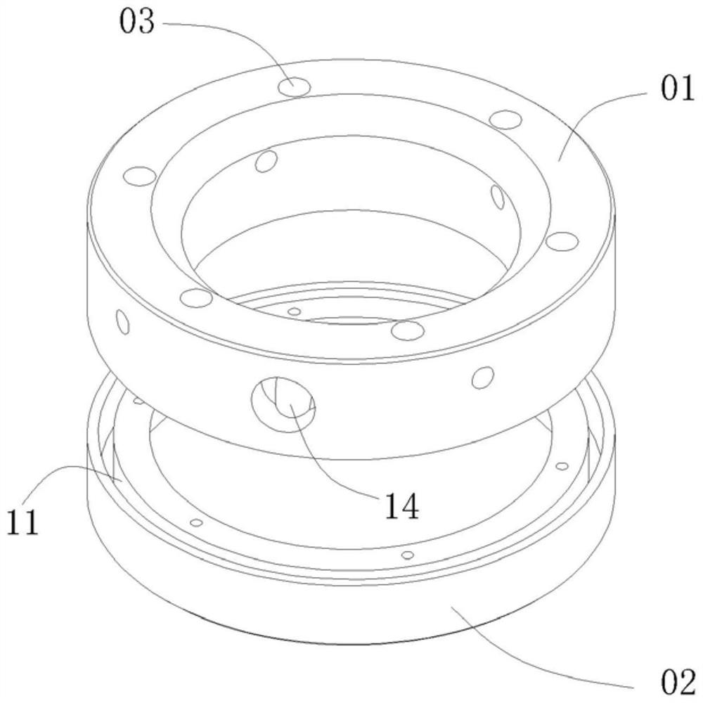
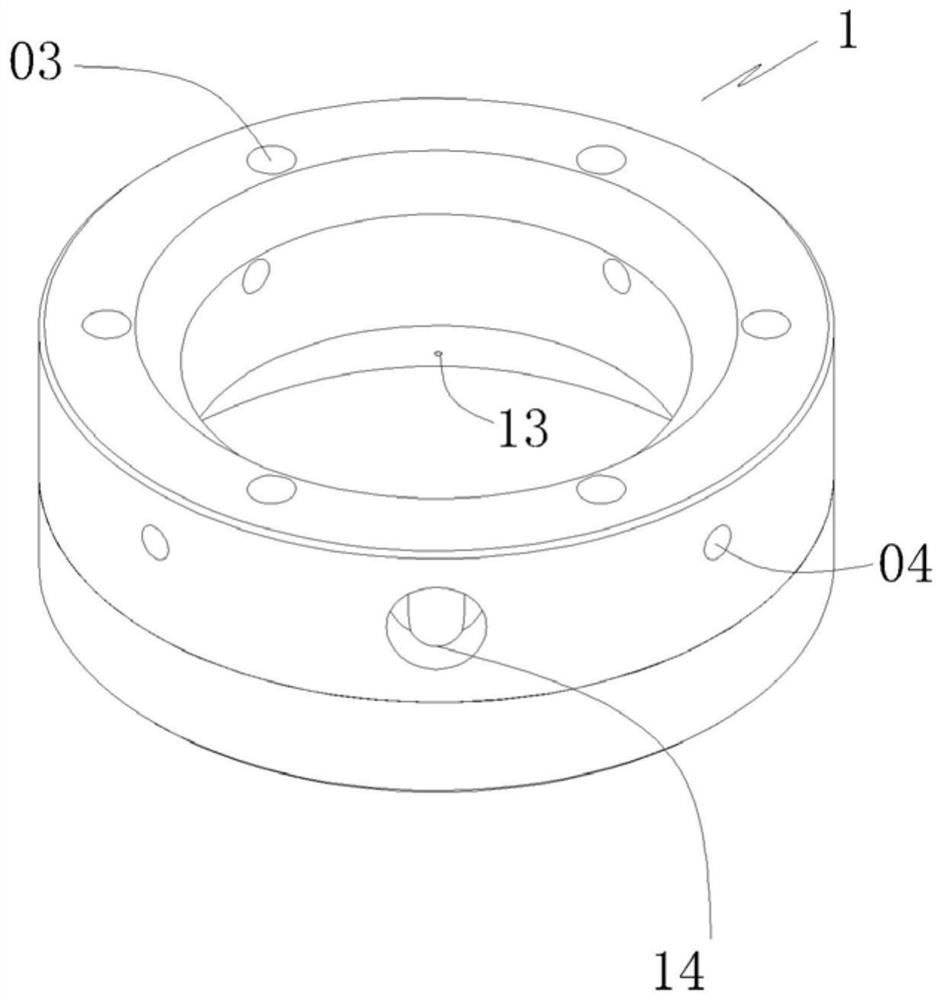
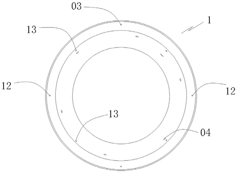
[0034] Please refer to Figure 1 to Figure 5 , a cooling water spray member for laser cutting in this embodiment, the spray member 1 is an annular cylindrical member with a vertical through hole in the middle, an annular water tank 11 is opened inside the spray member 1, and a bottom surface of the spray member 1 is provided with Several small spray holes 12 at the bottom of the annular water tank 11 are connected. The inner wall of the spray member 1 is provided with a number of small spray holes 13 on the side wall of the annular water tank 11. The outer wall of the spray member 1 is provided with water inlets 14. The annular water tank 11 It communicates with the water inlet hole 14; the spray member 1 is set on the outer periphery of the laser cutting head.

[0035] As a preferred embodiment, the lower part of the inner wall of the spray member 1 is set as an inverted cone surface, and the angle between the inverted cone surface and the vertical direction is 15°-45°; or, t...

Embodiment 2

[0043] Please refer to Figure 8 and Figure 9 , a cooling water spraying device for laser cutting in this embodiment, including the spraying member 1 described in the first embodiment.

[0044] And include: component water inlet valve 2, water delivery pipe 3 and water tank 4, component water inlet valve 2 is installed on the outside of spraying component 1, and the water outlet end of component water inlet valve 2 is connected with water inlet hole 14, and component water inlet valve 2 The water inlet end is connected with the water tank 4 through the water delivery pipe 3. The top of the water tank 4 is provided with an air blowing port 41, and the air blowing port 41 communicates with an external compressed air source.

[0045] Preferably, the top of the water tank 4 is provided with a water inlet 42 , the bottom of the water tank 4 is provided with a water outlet 43 , and the water delivery pipe 3 is connected to the water outlet 43 .

Embodiment 3

[0047] Please refer to Figure 1 to Figure 9 , a laser cutting machine of this embodiment, the laser cutting machine includes the cooling water spraying device as described in the second embodiment.


PUM


Abstract

The invention discloses a cooling water spraying member for laser cutting. An annular water tank is arranged inside the spraying member, and a plurality of bottom spraying holes communicating with the annular water tank are provided on the lower bottom surface of the spraying member. The inner side wall is provided with a number of side wall spray holes communicating with the annular water tank, and the outer wall of the spray member is provided with a water inlet hole, and the annular water tank is connected with the water inlet hole; the spray member is set on the On the outer periphery of the nozzle of the laser cutting head. The invention also discloses a cooling water spraying device for laser cutting and a laser cutting machine.

Description

technical field [0001] The invention relates to the technical field of laser cutting machinery and equipment, in particular to a cooling water spraying component for laser cutting, a cooling water spraying device for laser cutting and a laser cutting machine. Background technique [0002] Due to the high power and oxygen assistance in the process of cutting thick carbon steel, high-power laser cutting will cause the nozzle of the cutting head to become hot, and the overheating of the plate will affect the quality and stability of the cutting effect; especially the new cutting process Small hole nozzles and full high-power laser cutting can get good processing results, but the nozzles of the cutting head are the easiest to get hot. As long as the nozzles are hot, good processing quality cannot be achieved, and the stability is also poor. [0003] Currently CN208743919U discloses a laser cutting head water cooling protection device, which is arranged on the sensor of the laser...

Claims


Application Information

Patent Timeline
Patent Type & Authority Patents(China)
IPC IPC(8): B23K26/70B23K26/38
CPCB23K26/703B23K26/38
Inventor 吴胜涛邓世明吴兴旺
Owner 株洲特装智能装备有限公司
Why Eureka
Try Eureka