
Metal plate continuous printing and drying system

A printing drying and metal plate technology, applied in printing, printing machines, general parts of printing machinery, etc., can solve the problems of cumbersome operation, high labor intensity, trouble, etc., and achieve continuous printing drying, low labor intensity and easy operation simple effect

Active Publication Date: 2020-06-05
杭州吴杭包装材料有限公司
View PDF19 Cites 9 Cited by
  • Summary
  • Abstract
  • Description
  • Claims
  • Application Information

AI Technical Summary

Problems solved by technology

[0004] In the existing iron printing production process, drying is required after the iron printing technology, that is, the printed metal plate is moved to the oven for drying and curing, but because the metal plate is generally heavy, it is necessary to send the metal plate to the oven The process inside is particularly troublesome, labor-intensive, and its operation is cumbersome

Method used


Image

  • Metal plate continuous printing and drying system
  • Metal plate continuous printing and drying system
  • Metal plate continuous printing and drying system

Examples


Embodiment Construction

[0036] The present invention will be further described in detail below in conjunction with the drawings.

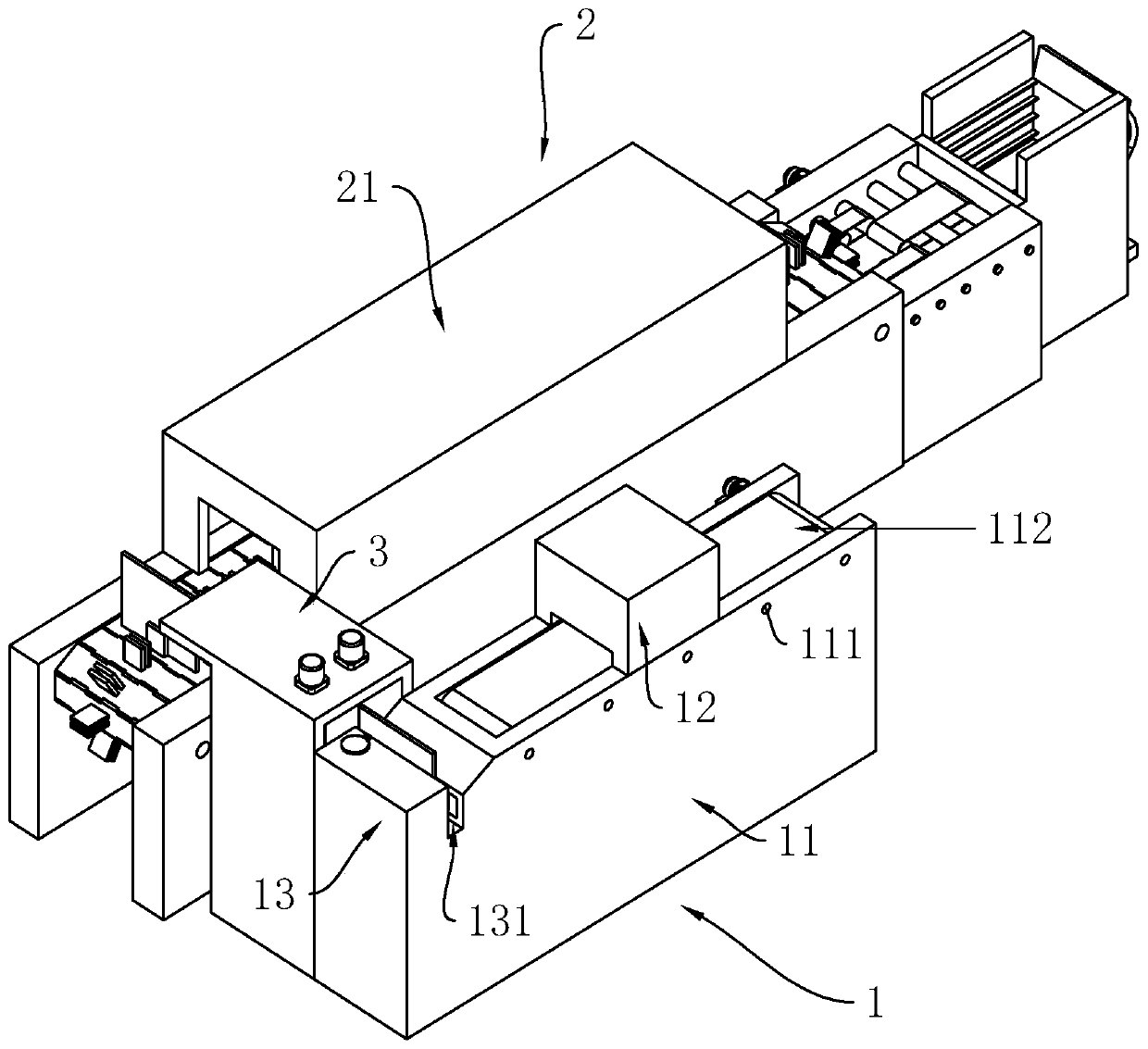
[0037] Reference figure 1 , Is a metal sheet continuous printing and drying system disclosed in the present invention, including a printing device 1, a drying device 2 and a transfer device 3.

[0038] The printing equipment 1 includes a conveying table 11, the upper side of the conveying table 11 is rotatably connected with a plurality of rotating rollers 111, the plurality of rotating rollers 111 are sleeved with a feeding belt 112, and the conveying table 11 is fixedly connected to the end of the feeding belt 112. There is a servo servo motor, and the output shaft of the servo motor is fixedly connected to the end of a rotating roller 111. The upper side of the middle of the conveying table 11 is also fixedly connected with a printing device 12 (here is the prior art and will not be repeated here), the discharge end of the conveying table 11 is fixedly connected with a disc...


PUM


Abstract

The invention relates to a metal plate continuous printing and drying system. The metal plate continuous printing and drying system comprises printing equipment, drying equipment and transfer equipment. The printing equipment comprises a conveying platform. A printing device is arranged in the middle of the conveying platform. The discharge end of the conveying platform is fixedly connected with adischarge platform. The middle of the discharge platform is provided with a discharge chute. A push plate is further vertically arranged on the side, close to the conveying platform, of the dischargechute. The side, opposite to the push plate, of the sidewall of the discharge chute is rotatably connected with feed rollers. The drying equipment comprises a drying oven. A chain plate conveyor beltis rotatably connected to the interior of the drying oven. The outer sides of each chain plate of the chain plate conveyor belt are fixedly connected with two locating racks. The transfer equipment comprises a transfer frame fixedly connected between the discharge chute of the discharge platform and the drying oven. The two sides of the transfer frame are rotatably connected with a plurality of chain wheels. The chain wheels on the two sides are sleeved with transmission chains correspondingly. The outer sides of the two transmission chains are uniformly and fixedly connected with clamping plates. The metal plate continuous printing and drying system has the advantages that the metal plate continuous printing and drying system automatically conveys printed iron plates to the drying equipment for printing without manual operation, reduces the labor intensity and is easy to operate.

Description

Technical field [0001] The invention relates to the technical field of continuous printing and drying equipment for iron plates, in particular to a continuous printing and drying system for metal plates. Background technique [0002] Printing iron is to print patterns on tinplate (tinned sheet). It mainly uses the physical properties of water and ink to repel each other, and with the help of printing pressure, the printing plate graphics and text are transferred to the tinplate via a blanket, which belongs to the principle of offset printing. [0003] The existing reference application publication number is: CN107627725A Chinese invention patent, which discloses an iron printing machine, including a machine, on both sides of the machine is provided with more than four sets of equidistant and symmetrical T-shaped connecting ribs, so One end of two sets of second electric telescopic rods is connected to the inner side of the protective plate, the other end of the second electric tel...

Claims


Application Information

Patent Timeline
Patent Type & Authority Applications(China)
IPC IPC(8): B41F23/04B65G47/24B65G17/46B65G17/06
CPCB41F23/0443B41F23/0466B65G17/06B65G17/46B65G47/24
Inventor 雷代新郑木华李波丁云能
Owner 杭州吴杭包装材料有限公司
Learn More