Vehicle thermal management system, control method thereof and vehicle

A thermal management system, vehicle technology, applied in the vehicle thermal management system and its control method, and the field of vehicles, can solve the problems of increasing the energy consumption burden of the whole vehicle, heat waste, slow cooling efficiency, etc.

Active Publication Date: 2020-06-05
BYD CO LTD
View PDF6 Cites 12 Cited by
  • Summary
  • Abstract
  • Description
  • Claims
  • Application Information

AI Technical Summary

Problems solved by technology

The existing engine thermal management circuit and the battery system circuit are relatively independent, and the intercommunication between the circuits cannot be realized, so the heating of the battery by the engine cannot be realized
In addition, the existing electric drive thermal management system is independent of the air conditioner thermal management system and the battery thermal management system. The heating of the battery mainly depends on the battery heater for heating. Radiator for heat dissipation, resulting in waste of heat
When the cooling demand of the motor or electronic control is high, the cooling efficiency is slow and the effect is poor if only the radiator is used to cool down
In addition, the cooling of the battery mainly depends on the thermal management system of the air conditioner. Even when the cooling demand of the battery is low and the passenger compartment has no cooling demand, the thermal management system of the air conditioner needs to be activated, which also increases the energy consumption burden of the vehicle.

Method used


Image

  • Vehicle thermal management system, control method thereof and vehicle
  • Vehicle thermal management system, control method thereof and vehicle
  • Vehicle thermal management system, control method thereof and vehicle

Examples


Embodiment Construction

[0025] Specific embodiments of the present disclosure will be described in detail below in conjunction with the accompanying drawings. It should be understood that the specific embodiments described here are only used to illustrate and explain the present disclosure, and are not intended to limit the present disclosure.

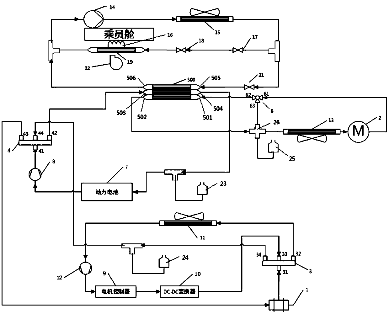
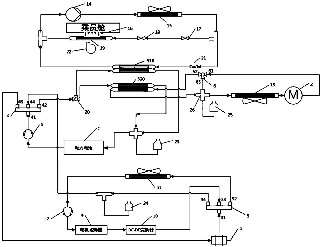
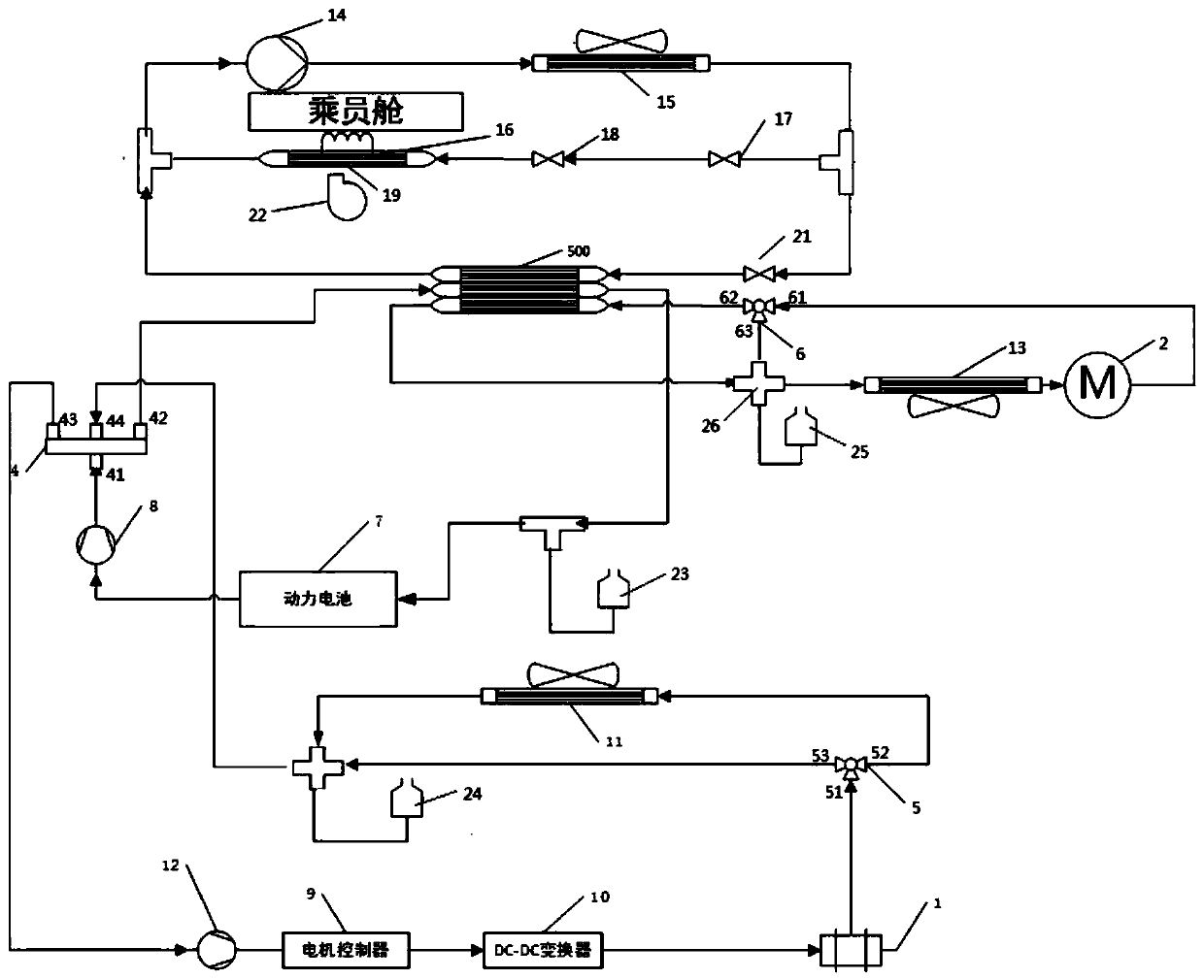
[0026] In this disclosure, unless stated to the contrary, the use of orientation words such as "refrigerant inlet, cooling liquid inlet, refrigerant outlet and cooling liquid outlet" are generally relative to the flow direction of a fluid such as refrigerant or cooling liquid. Specifically, the openings through which fluid flows into components in the thermal management system of vehicles such as condensers, batteries, and evaporators are "refrigerant inlets and coolant inlets". The outflow openings of components in the thermal management system are "refrigerant outlets and coolant outlets".

[0027] Such as Figure 1 to Figure 3 As shown, the present discl...


PUM


Abstract

The invention relates to a vehicle thermal management system, a control method thereof and a vehicle. The vehicle thermal management system comprises a battery and electric drive thermal management system and an engine thermal management system. The air conditioning system exchanges heat with the battery and electric drive heat management system through a heat exchanger; the engine heat managementsystem comprises an engine cooling liquid flow path trunk, a first engine cooling liquid flow path branch and a second engine cooling liquid flow path branch, an engine and a first radiator are arranged on the engine cooling liquid flow path main circuit. The engine cooling liquid flow path main path is selectively communicated with the engine cooling liquid flow path first branch path or the engine cooling liquid flow path second branch path, and the engine cooling liquid flow path first branch path exchanges heat with the battery and electric drive heat management system through a heat exchanger. When the vehicle is in a hybrid drive mode, the battery may be heated with the engine.

Description

technical field [0001] The present disclosure relates to the field of vehicle thermal management systems, in particular, to a vehicle thermal management system, a control method thereof, and a vehicle. Background technique [0002] In the vehicle thermal management system of hybrid electric vehicles, it includes air-conditioning thermal management system, battery thermal management system, electric drive thermal management system and engine thermal management system. The existing engine thermal management circuit and the battery system circuit are relatively independent, and the intercommunication between the circuits cannot be realized, so the heating of the battery by the engine cannot be realized. In addition, the existing electric drive thermal management system is independent of the air conditioner thermal management system and the battery thermal management system. The heating of the battery mainly depends on the battery heater for heating. The radiator dissipates hea...

Claims


Application Information

Patent Timeline
Patent Type & Authority Applications(China)
IPC IPC(8): B60K11/04H01M10/613H01M10/615H01M10/625
CPCB60K11/04H01M10/613H01M10/615H01M10/625Y02E60/10
Inventor 凌和平董莹王刚宋鹏辉陈昊
Owner BYD CO LTD
Why Eureka
Try Eureka