Clutch and paver
A technology of clutch and clutch components, applied in the field of transmission, can solve problems such as heavy engine load, engine failure to start, and normal construction
- Summary
- Abstract
- Description
- Claims
- Application Information
AI Technical Summary
Problems solved by technology
Method used
Image


Examples
Embodiment 1
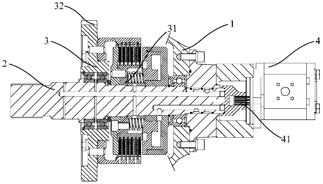
[0044] In this embodiment, a clutch is provided, such as figure 1 As shown, it includes a box body 1 (part of the structure of the box body 1 is omitted in the figure), an input shaft 2, a clutch assembly 3, and a hydraulic oil pump 4. The input shaft 2 passes through the box body 1 and is rotatably connected with the box body 1; one end of the input shaft 2 can be drivingly connected with the output shaft of the engine, and the other end extends from the box body 1 outward. The clutch assembly 3 is arranged in the box 1 and sleeved on the outer side of the input shaft 2 in the radial direction. The first end 31 of the clutch assembly 3 is fixedly connected with the input shaft 2, and the second end 32 of the clutch assembly 3 is used for outward Output power and rotatably connect with the input shaft 2; the second end 32 can be connected or disconnected with the first end 31, and when the second end 32 is connected to the first end 31, the second end 32 can be with the input sh...
Embodiment 2
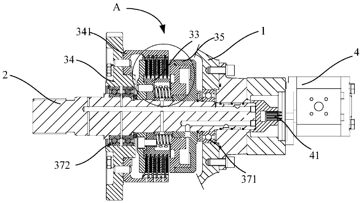
[0046] In this embodiment, a clutch is provided, such as figure 1 As shown, it includes a box body 1 (part of the structure of the box body 1 is omitted in the figure), an input shaft 2, a clutch assembly 3, and a hydraulic oil pump 4. The input shaft 2 passes through the box body 1 and is rotatably connected with the box body 1 through the first bearing 371; one end of the input shaft 2 can be drivingly connected with the output shaft of the engine, and the other end extends from the box body 1 outward. The clutch assembly 3 is arranged in the box 1 and sleeved on the outside of the input shaft 2 in the radial direction. The clutch assembly 3 includes an outer gear 33, an inner gear 34, a piston cylinder 35 and a return spring 36. The outer gear ring 33, the inner gear ring 34 and the piston cylinder 35 are all sleeved on the outside of the input shaft 2, where, such as image 3 As shown, the outer ring gear 33 and the piston cylinder 35 are fixedly connected to the input shaft...
Embodiment 3
[0049] This embodiment provides a clutch, which is further improved on the basis of the second embodiment. Such as Figure 4 As shown, the clutch also includes an oil distribution plate 5, which is arranged between the box body 1 and the hydraulic oil pump 4 and sleeved on the outside of the input shaft 2. The oil distribution plate 5 and the box body 1 are fixedly connected by bolts. The oil distribution pan 5 is provided with a first interface 51 which communicates with the hydraulic oil pump 4 through a pipeline. Such as Figure 5 with Image 6 As shown, the position on the input shaft 2 corresponding to the first interface 51 is provided with an annular first groove 211 along the circumferential direction of the input shaft 2, and the first groove 211 is in communication with the first interface 51. The input shaft 2 is provided with a first oil passage 212 extending in the axial direction. The first oil passage 212 and the first groove 211 are communicated through the firs...
PUM
 Abstract
Description
Claims
Application Information
 - R&D
- Intellectual Property
- Life Sciences
- Materials
- Tech Scout
- Unparalleled Data Quality
- Higher Quality Content
- 60% Fewer Hallucinations
Browse by: Latest US Patents, China's latest patents, Technical Efficacy Thesaurus, Application Domain, Technology Topic, Popular Technical Reports.
© 2025 PatSnap. All rights reserved.Legal|Privacy policy|Modern Slavery Act Transparency Statement|Sitemap|About US| Contact US: help@patsnap.com