Electromagnetic adjustable vibration damper

A shock absorber and electromagnetic technology, applied in the direction of spring/shock absorber, spring/shock absorber design features, coil spring, etc., can solve problems such as real-time adjustment of shock absorber strength without specific solutions, and achieve response Sensitive, avoid high temperature work, reduce wear effect

Inactive Publication Date: 2020-06-05
FOSHAN UNIVERSITY
View PDF8 Cites 2 Cited by
  • Summary
  • Abstract
  • Description
  • Claims
  • Application Information

AI Technical Summary

Problems solved by technology

[0004] It can be seen that there are still many concrete solutions that have not been proposed for the practical problems (real-time adjustment of the strength of the shock absorber, etc.) that need to be dealt with in its practical application.

Method used


Image

  • Electromagnetic adjustable vibration damper
  • Electromagnetic adjustable vibration damper
  • Electromagnetic adjustable vibration damper

Examples


Embodiment 1

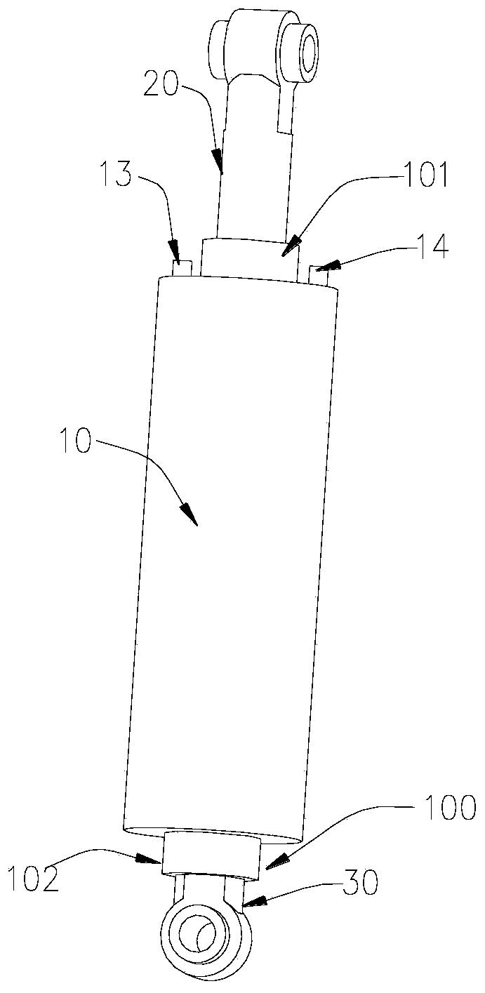
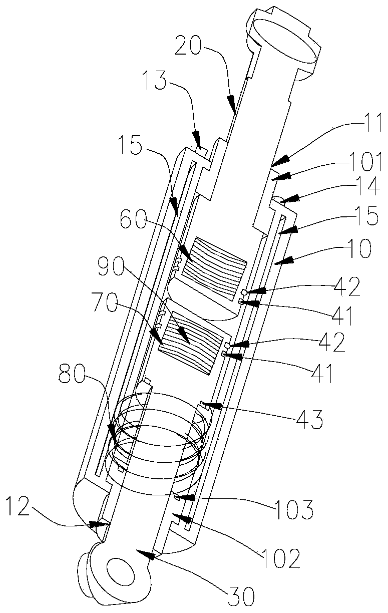
[0027] An electromagnetic adjustable shock absorber, such as Figure 1-4 Shown, comprise cylinder body 10, first piston device 20, second piston device 30, described first piston device 20 and described second piston device 30 all comprise piston head 40 and piston rod 50, described cylinder body 10 One end of the cylinder body 10 is provided with a first through hole 11, and the other end of the cylinder body 10 is provided with a second through hole 12, and the lower end of the piston rod 50 of the first piston device 20 extends into the upper part of the inner cavity of the cylinder body 10. The upper end of the piston rod 50 of the second piston device 30 extends into the lower part of the inner cavity of the cylinder body 10, the first through hole 11 is matched with the outer circle of the piston rod 50 of the first piston device 20, and the second through hole 12 is matched with the first piston rod 50 of the first piston device 20. The piston rods 50 of the two piston ...

Embodiment 2

[0031] An electromagnetic adjustable shock absorber, such as Figure 1-4 Shown, comprise cylinder body 10, first piston device 20, second piston device 30, described first piston device 20 and described second piston device 30 all comprise piston head 40 and piston rod 50, described cylinder body 10 One end of the cylinder body 10 is provided with a first through hole 11, and the other end of the cylinder body 10 is provided with a second through hole 12, and the lower end of the piston rod 50 of the first piston device 20 extends into the upper part of the inner cavity of the cylinder body 10. The upper end of the piston rod 50 of the second piston device 30 extends into the lower part of the inner cavity of the cylinder body 10, the first through hole 11 is matched with the outer circle of the piston rod 50 of the first piston device 20, and the second through hole 12 is matched with the first piston rod 50 of the first piston device 20. The piston rods 50 of the two piston ...

Embodiment 3

[0037] An electromagnetic adjustable shock absorber, such as Figure 1-4 Shown, comprise cylinder body 10, first piston device 20, second piston device 30, described first piston device 20 and described second piston device 30 all comprise piston head 40 and piston rod 50, described cylinder body 10 One end of the cylinder body 10 is provided with a first through hole 11, and the other end of the cylinder body 10 is provided with a second through hole 12, and the lower end of the piston rod 50 of the first piston device 20 extends into the upper part of the inner cavity of the cylinder body 10. The upper end of the piston rod 50 of the second piston device 30 extends into the lower part of the inner cavity of the cylinder body 10, the first through hole 11 is matched with the outer circle of the piston rod 50 of the first piston device 20, and the second through hole 12 is matched with the first piston rod 50 of the first piston device 20. The piston rods 50 of the two piston ...


PUM


Abstract

The invention provides an electromagnetic adjustable vibration damper, and belongs to the technical field of vibration dampers. The electromagnetic adjustable vibration damper comprises a cylinder body, a first piston device and a second piston device; the first piston device and the second piston device each comprises a piston head and a piston rod; one end of the cylinder body is provided with afirst through hole, and the other end of the cylinder body is provided with a second through hole; one end of the first piston device is internally provided with a first electromagnetic coil; one endof the second piston device is internally provided with a second electromagnetic coil, and the middle of the second piston device is sleeved with a spring; the interior of the first piston device andthe interior of the second piston device are both provided with adjusting systems for controlling the magnitude of currents of the first electromagnetic coil and the second electromagnetic coil; theadjusting systems are electrically connected with the first electromagnetic coil and the second electromagnetic coil; and vibration damper strength control is achieved, the elongation of the vibrationdamper is controllable, and the very good practicality is achieved.

Description

technical field [0001] The invention relates to the technical field of shock absorbers, in particular to an electromagnetic adjustable shock absorber. Background technique [0002] In today's society, shock absorbers are used in more and more complex scenes, especially shock absorbers used on robots. Shock absorbers play an increasingly important role in people's lives, but the existing technology The shock absorber structure of the shock absorber system includes springs and hydraulic cylinders, which have the disadvantages of slow response and non-adjustable strength. Different shock absorbers need to be designed for each usage scenario, which seriously affects the manufacturing cost and the scope of promotion. [0003] After searching, it is found that some typical prior art, such as the patent application number 201610704410.3, discloses a shock absorber. When the first shaft tube rotates relative to the seat body and the abutting piece corresponds to the groove, the abut...

Claims


Application Information

Patent Timeline
IPC IPC(8): F16F1/12
CPCF16F1/121F16F2230/18
Inventor 刘坤达范启东卢育健
Owner FOSHAN UNIVERSITY
Why Eureka
Try Eureka