A measuring apparatus for nanometer magnetic materials and a method thereof

A nano-magnetic material and measurement device technology, applied in the field of measurement, can solve problems such as measurement accuracy below 10nm, inability to observe weakly magnetic samples, and harsh experimental conditions, so as to improve detection accuracy and sensitivity, enhance magnetic interaction, and achieve universal strong effect

Active Publication Date: 2016-06-22
SUN YAT SEN UNIV
View PDF5 Cites 3 Cited by
  • Summary
  • Abstract
  • Description
  • Claims
  • Application Information

AI Technical Summary

Problems solved by technology

However, most of these magnetic material measurement devices require a large external magnetic field and the experimental conditions are relatively harsh, and the versatility is not strong; and the measurement accuracy in the atmospheric environment cannot reach below 10nm, and it cannot be used for nanoscale weak magnetic samples (such as superparamagnetic nanoparticles) for accurate observation

Method used


Image

  • A measuring apparatus for nanometer magnetic materials and a method thereof
  • A measuring apparatus for nanometer magnetic materials and a method thereof
  • A measuring apparatus for nanometer magnetic materials and a method thereof

Examples


Embodiment 1

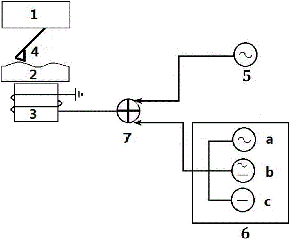
[0052] Such as figure 1 As shown, the core composition of the measuring device involved in the present invention mainly includes a magnetic sample to be measured 2, a first electromagnetic coil 3, a detection magnetic field excitation device 5, a modulation magnetic field controller 6, an adder 7, a magnetic force microscope control part 1 and Magnetic probe 4. Among them, the modulated magnetic field controller 6 also includes three optional gears, namely, the alternating magnetic field modulation part a, the mixed magnetic field modulation part b and the constant magnetic field modulation part c. The three positions are equal and can be freely selected by the user.

[0053] The interrelationship of the above-mentioned components is: the first electromagnetic coil 3 generates a magnetic field with a variable intensity under the drive of the modulation magnetic field controller 6 to produce a magnetic modulation effect on the magnetic sample 2 to be measured, and then passes t...

Embodiment 2

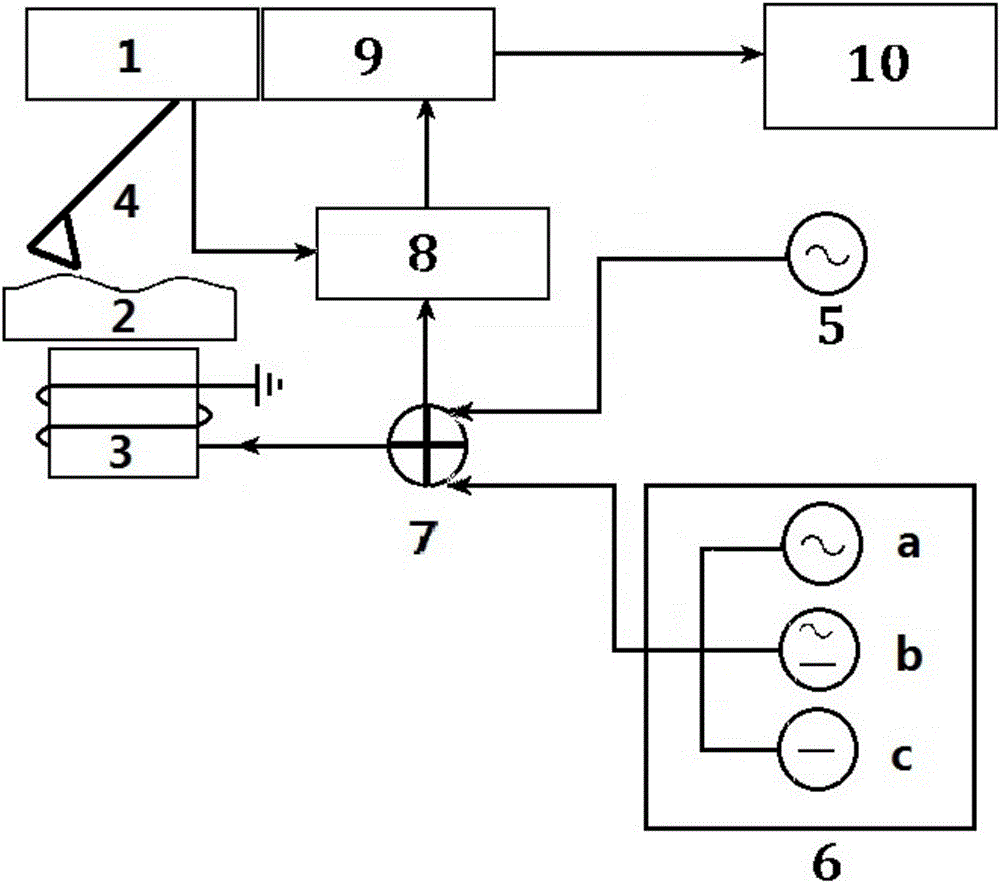
[0061] Such as Figure 5 As shown, the first preferred example of the present invention is an application example equipped with a multi-frequency magnetic force microscope. The components of this preferred example mainly include: microscope support 11, magnetic probe 4, detector 16, first electromagnetic coil 3, scanner 17, modulation magnetic field controller 6, detection magnetic field excitation device 5, magnetic force signal detector 8 , adder 7, controller 12 and display 10; The magnetic probe 4, detector 16 and scanner 17 are all installed on the magnetic force microscope support 11, and the first electromagnetic coil 3 is placed directly above the scanner 17 , the measured sample 2 is placed directly above the first electromagnetic coil 3, and the magnetic probe 4 is located directly above the measured sample 2; the modulation magnetic field controller 6 is used to generate an excitation signal for regulating and modulating the intensity of the modulation magnetic fiel...

Embodiment 3

[0071] In addition to the example of combining with a multi-frequency magnetic force microscope, the magnetic force microscope carried by the present invention can also be any existing magnetic force microscope, such as a two-pass scanning magnetic force microscope. Compared with the example of the combination of the present invention and the existing two-pass scanning magnetic force microscope, its basic structure diagram is compared with the example of the combination of the present invention and the multi-frequency magnetic force microscope, the main difference is that the magnetic probe 4 is no longer separately modulated by the electromagnetic coil at the same time Driven, and the scanning process is a two-pass scanning mode: the first pass scanning obtains the topography map, and the second pass scan obtains the magnetic force map of the modulated magnetic sample.

[0072] Such as Figure 6 As shown, the embodiment of the present invention combined with the magnetic forc...


PUM


Abstract

The invention discloses a measuring apparatus for nanometer magnetic materials and a method thereof. The apparatus comprises a detected magnetic sample, a first solenoid, a modulation magnetic field controller, a magnetic probe, a detection magnetic field exciting apparatus and a magnetic force microscope control portion. The magnetic probe is positioned right above the detected magnetic sample. The first solenoid generates an alternating magnetic field under driving of the detection magnetic field exciting apparatus to enable the magnetic probe to undergo magnetic excitation with a corresponding frequency and carry out vibration at the frequency. The first solenoid generates the modulation magnetic field with controllable intensity under the driving of the modulation magnetic field controller, carries out magnetic modulation on the detected magnetic sample and carries out magnetic force imaging on the detected magnetic sample through the magnetic probe carried by the magnetic force microscope control portion. The apparatus and the method of the invention is strong in universality, and is suitable for carrying out accurate observation on samples presenting weak magnetism, especially superparamagnetism in atmosphere environment and at a room temperature. The invention can be widely applied to the field of measurement technology.

Description

technical field [0001] The invention relates to the field of measurement technology, in particular to a measurement device and method for nanometer magnetic materials. Background technique [0002] At present, the magnetic measurement methods for materials mainly include: [0003] a. The traditional magnetic force microscope (Magnetic Force Microscope, referred to as MFM), by capturing the magnetic interaction between the magnetic probe and the magnetic sample for magnetic imaging, can reflect the magnetic flux leakage and its two-dimensional distribution on the surface of the sample. It is a kind of magnetic material An important tool for the simultaneous characterization of microstructural and magnetic properties. At present, the imaging of the magnetic force microscope usually adopts the method of two-pass scanning. Due to the large distance between the probe and the sample in the magnetic force imaging, its lateral resolution is usually lower than that of the atomic for...

Claims


Application Information

Patent Timeline
Patent Type & Authority Applications(China)
IPC IPC(8): G01Q60/50
CPCG01Q60/50
Inventor 丁喜冬
Owner SUN YAT SEN UNIV
Why Eureka
Try Eureka