Single-stage densely-arranged combined tooth surface cycloid oscillating tooth transmission unit

A technology of movable tooth transmission and tooth surface, applied in the field of movable tooth transmission, can solve the problems of inability to improve the performance of the reducer, insufficient space utilization, unsatisfactory power density, etc., and achieve flexible design, large bearing capacity, and impact resistance. powerful effect

Inactive Publication Date: 2020-06-05
HENAN ZHULONG HI TECH CO LTD
View PDF12 Cites 4 Cited by
  • Summary
  • Abstract
  • Description
  • Claims
  • Application Information

AI Technical Summary

Problems solved by technology

However, in the case of following the traditional design methods and rules, the power density of the designed reducer is not ideal. Generally speaking, it is large in size, relatively small in transmission ratio, and insufficient in space utilization.
All the existing research and optimization are based on the condition that the meshing pair is not undercut. The general optimization is to optimize the parameters and modify the tooth shape, which has great limitations and cannot be used for the reducer. to significantly improve performance

Method used


Image

  • Single-stage densely-arranged combined tooth surface cycloid oscillating tooth transmission unit
  • Single-stage densely-arranged combined tooth surface cycloid oscillating tooth transmission unit
  • Single-stage densely-arranged combined tooth surface cycloid oscillating tooth transmission unit

Examples


Embodiment Construction

[0047] The following will clearly and completely describe the technical solutions in the embodiments of the present invention with reference to the accompanying drawings in the embodiments of the present invention. Obviously, the described embodiments are only some, not all, embodiments of the present invention. Based on the embodiments of the present invention, all other embodiments obtained by persons of ordinary skill in the art without making creative efforts belong to the protection scope of the present invention.

[0048] Figure 23 to Figure 26 It is the first embodiment of the present invention. In this embodiment, the meshing curve adopts the epicycloid in the plane, and the movable tooth adopts a standard sphere. From Figure 23 and Figure 24 It can be seen that the wave number of the combined tooth surface raceway is 15, and the number of movable teeth, contact groove surface and non-contact groove surface is 16; from Figure 25 and Figure 26 It can be seen tha...


PUM


Abstract

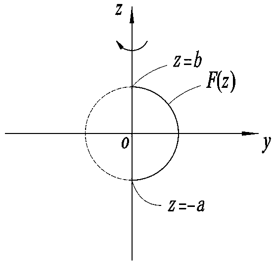
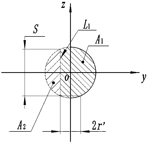
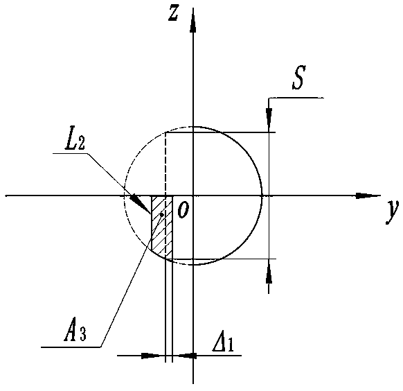
The invention provides a single-stage densely-arranged combined tooth surface cycloid oscillating tooth transmission unit which comprises oscillating teeth, a combined tooth surface transmission wheel, a combined groove surface transmission wheel and the like. On the basis of cycloid oscillating tooth transmission, the radius of the oscillating tooth distribution circle is firstly confirmed, and under the condition that the radius of the oscillating tooth distribution circle is definite, the size of oscillating teeth capable of densely arranged on the distribution circle by a whole circle is unique and definite; then, a roller way with a large roller way amplitude is selected, the engagement curve of the roller way meets the undercut condition, on the basis, the oscillating tooth section is subjected to discretization into four different sections, each section is swept along the hypocycloid or the epicycloids to obtain a corresponding engaged tooth surface or spins along the edge to obtain the corresponding tooth surface, the three specific tooth surfaces are combined into a whole, and the combined tooth surface roller way is formed; a combined groove on the combined groove surfacetransmission wheel is formed by contact groove surfaces an noncontact groove surfaces of the same number; and the densely-arranged combined tooth surface cycloid oscillating tooth transmission unit is jointly formed by the combined tooth surface transmission wheel, the oscillating teeth and the combined groove surface transmission wheel.

Description

technical field [0001] The invention relates to the technical field of movable tooth transmission, in particular to a single-stage close-packed combined tooth surface cycloid movable tooth transmission unit. Background technique [0002] With the development of movable tooth transmission technology, various movable tooth transmission configurations emerge in endlessly, such as push rod movable tooth transmission, roller (steel ball) movable tooth transmission, swing movable tooth transmission, sleeve movable tooth transmission and Planar steel ball transmission, etc.; no matter what form of movable tooth transmission technology, its core and essence is the movement of the movable tooth along its meshing curve, and the space track surface obtained by the movable tooth moving along the meshing curve is the actual movable tooth meshing tooth In the traditional movable tooth design, the actual meshing tooth surface is continuous and avoids undercutting. For example, the patent ...

Claims


Application Information

Patent Timeline
Patent Type & Authority Applications(China)
IPC IPC(8): F16H1/32F16H55/17F16H55/08
CPCF16H1/32F16H55/08F16H55/17F16H2055/176
Inventor 闫济东邢鹏达
Owner HENAN ZHULONG HI TECH CO LTD
Why Eureka
Try Eureka