Deicing method and device of dehumidifier defrosting tray

A water-receiving pan and dehumidifier technology, applied in refrigerators, compressors, heating methods, etc., can solve the problems of energy waste, freezing of water-receiving pans, and easy frosting of dehumidifiers, so as to achieve good energy-saving effect and maintain reliability. sexual effect

Pending Publication Date: 2020-06-05
宁波德业日用电器科技有限公司
0 Cites 1 Cited by

AI-Extracted Technical Summary

Problems solved by technology

[0004] The current dehumidifiers are prone to frosting when operating at low temperatures, and generally need to be defrosted. During the defrosting process, due to the low temperature, it is easy to cause the water tray to freeze. Therefore, a heating wire is installed at the bott...

Method used

The present invention is by compressor 3 being placed on the below of water tray 7, then by the heat that compressor 3 produces when working, the ice that produces on water tray 7 is carried out deicing treatment, to realize without adding heater in the later stage The energy-saving effect of realizing ice melting is better. The present invention does not need to use heating devices such as heaters, and uses the waste heat of the compressor to dissolve the ice on the water tray, so as to...

Abstract

The invention discloses a deicing device of a dehumidifier defrosting tray. The deicing device comprises a dehumidifier body, a first heat exchanger, a second heat exchanger, a compressor, a pressurereducer, a draught fan, a four-way reversing valve and a temperature detector are arranged in the dehumidifier body, wherein the temperature detector is arranged on the first heat exchanger. The draught fan is located at the rear end of the second heat exchanger, the first heat exchanger is located at the front end of the second heat exchanger, two ends of the first heat exchanger are correspondingly connected with the pressure reducer and one end of the four-way reversing valve, two ends of the second heat exchanger are correspondingly connected with the pressure reducer and the other end ofthe four-way reversing valve, the other two ends of the four-way reversing valve are connected with the two ends of the compressor, the defrosting tray is arranged below the first heat exchanger and the second heat exchanger, and the compressor is located below the defrosting tray. The invention further discloses a deicing method of the dehumidifier defrosting tray. The energy-saving effect is achieved.

Application Domain

Mechanical apparatusCondensate prevention +4

Technology Topic

PhysicsEngineering +3

Image

  • Deicing method and device of dehumidifier defrosting tray
  • Deicing method and device of dehumidifier defrosting tray
  • Deicing method and device of dehumidifier defrosting tray

Examples

  • Experimental program(1)

Example Embodiment

[0039] Example 1:
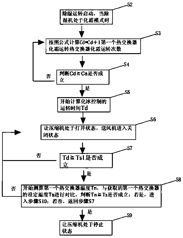
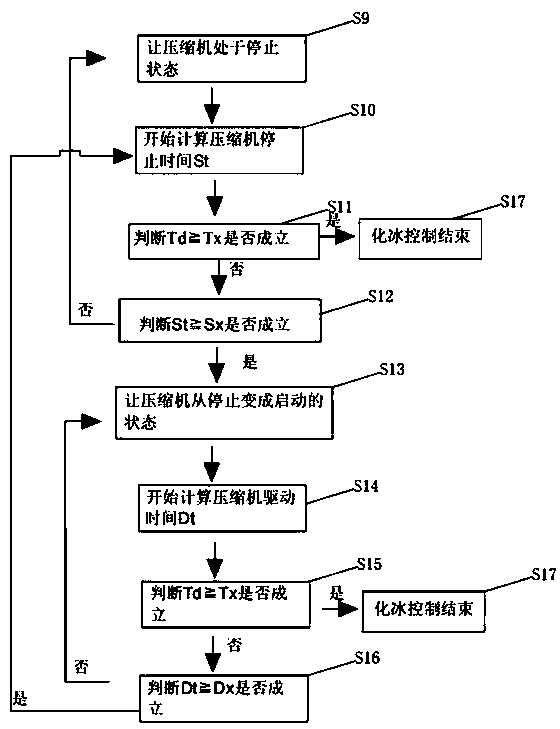
[0040] Such as Figure 1-Figure 2 As shown, the method for deicing the water tray of a dehumidifier provided in this embodiment specifically includes the following steps:
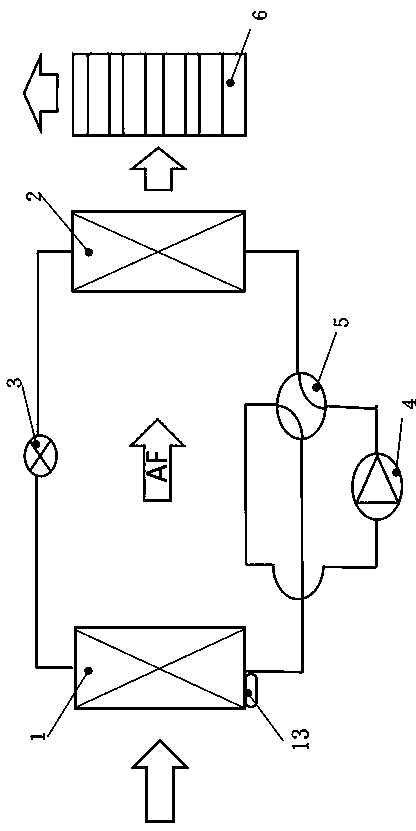
[0041] S1. Provide a dehumidifier, which includes a first heat exchanger, a second heat exchanger, a compressor, a pressure reducer, a fan, a four-way reversing valve, and a temperature detector provided on the first heat exchanger;
[0042] S2, the dehumidification operation starts, when the dehumidifier is in defrosting mode;
[0043] S3. Accumulate the number of dehumidification times by the formula Cd=Cd+1 to obtain the number of defrosting operations Cd of the first heat exchanger;
[0044] S4. Obtain the preset number of heat exchanger defrosting times Cs, and judge whether Cd≧Cs is established; if yes, go to step S5; if not, go back to step S2;
[0045] S5. It is considered that the ice removal control of the water receiving tray is started, and the operation time Td of the ice removal control is calculated at this time;
[0046] S6. Let the compressor be in the on state and the blower into the off state;
[0047] S7. Obtain the preset deicing control time Ts1, and judge whether Td≧Ts1 is established; if yes, go to step S8; if not, go back to step S6;
[0048] S8. Start measuring the temperature Tn of the first heat exchanger, and compare it with the acquired set temperature Ts of the first heat exchanger to determine whether Tn≧Ts is established; if yes, go to step S9; if not, go back to step S6;
[0049] S9. Let the compressor be stopped;
[0050] S10. Start calculating the compressor stop time St;
[0051] S11. Judge whether Td≧Tx is established, the Tx is the preset deicing control time Tx, if yes, go to step S17; if not, go to step S12;
[0052] S12. Determine whether St≧Sx is established, the Sx is the preset compressor stop time Sx, if yes, go to step S13; if not, go to step S9;
[0053] S13. Let the compressor change from stop to start;
[0054] S14. Start calculating the compressor driving time Dt;
[0055] S15. Judge whether Td≧Tx is established, the Tx is the preset deicing control time Tx, if yes, go to step S17; if not, go to step S16;
[0056] S16. Determine whether Dt≧Dx is established. The Dx is the preset compressor driving time Dx. If yes, go to step S10; if not, go to step S13;
[0057] S17. The deicing control ends.
[0058] The present invention first obtains the data of the number of defrosting times when the water receiving tray is frozen at this time through experiments, and then presets the defrost times corresponding to the freezing of the water receiving tray and stores them, and then defrosts them later. At the beginning, the number of defrosts is monitored in real time and compared with the preset number of defrosts Cd. Once the number of defrosts obtained in real time is greater than the preset number of defrosts (that is, the requirement for deicing is reached), the compressor is started to generate heat , The heat rises and the ice on the water tray is deiced. At this time, the deicing operation time Td is obtained, and it is judged with the preset deicing time. Compared with the calculation of the first heat exchanger temperature Tn and the preset temperature mechanical energy comparison The process of deicing can be judged whether the deicing can be completed, and the present invention prolongs the service life of the compressor by intermittently controlling the stop or start of the compressor during the entire control process, and ensures that the compressor is not in the deicing process for a long time. Starting state, therefore, the method of the present invention can realize the real-time detection of the number of defrosts to determine the icing state of the water receiving tray, and when the preset icing requirement is reached, the compressor is controlled to start and stop intermittently to realize the automatic operation of the water receiving tray deicing During the process, there is no need to add a heating device to realize the deicing operation process of the docking water tray, and the compressor is controlled intermittently to ensure that the compressor is damaged due to long-term use, and ultimately prolong the service life of the compressor.
[0059] Such as Figure 3-5 As shown, this embodiment also discloses a deicing device for the water receiving tray of a dehumidifier, which includes a dehumidifier body 14, in which a first heat exchanger 1, a second heat exchanger 2, and a compression The machine 3, the pressure reducer 4, the fan 5, the four-way reversing valve 6 and the temperature detector 13 arranged on the first heat exchanger 1. The fan 5 is located at the rear end of the second heat exchanger 2, so The first heat exchanger 1 is located at the front end of the second heat exchanger 2. The two ends of the first heat exchanger 1 are respectively connected to the pressure reducer 4 and one end of the four-way reversing valve 6, and the second heat exchange The two ends of the device 2 are respectively connected to the pressure reducer 4 and the other end of the four-way reversing valve 6, the other two ends of the four-way reversing valve 6 are connected to both ends of the compressor 3, in the first heat exchanger 1, A water receiving pan 7 is provided below the second heat exchanger 2, and the compressor 3 is located below the water receiving pan 7.
[0060] Further, in order to facilitate installation, the four-way reversing valve 6 is located below the water receiving tray 7.
[0061] Further, in order to improve the effect of deicing, the first heat exchanger 1 and the second heat exchanger 2 are mounted on a mounting bracket 8, and the water receiving tray 7 and the mounting bracket 8 are integrally formed.
[0062] Further, in order to improve the effect of deicing, a compressor accommodating cavity 9 blocked on both sides is provided in the mounting bracket 8. The compressor accommodating cavity 9 and the outer shell of the dehumidifier body 14 form a heat storage bin 10. The heat storage bin 10 is located below the water receiving tray 7, and above the compressor containing cavity 9 is an outlet 11 communicating with the bottom of the water receiving tray 7.
[0063] Further, to avoid heat diffusion and affect the effect of deicing, two sides of the bottom of the water receiving tray 7 are respectively provided with heat shields 12 to prevent heat diffusion, and the heat shields 12 are located outside the outlet 11.
[0064] Furthermore, the efficiency of deicing is improved, and the effect of energy saving is further realized. The diameter of the outlet 11 of the compressor containing chamber 9 is equal to one-half of the diameter of the bottom of the water receiving pan 7.
[0065] In the present invention, the compressor 3 is placed under the water receiving tray 7, and then the ice generated on the receiving water tray 7 is deiced by the heat generated by the compressor 3 during operation, so as to realize the deicing without adding a heater in the later stage. The energy-saving effect is better. The present invention uses the waste heat of the compressor to dissolve the ice on the water tray without using heaters and other heating devices, and realizes continuous dehumidification operation in a sub-zero environment. The compressor as the heat source is set In the lower part of the dehumidification device (condensation water generating device) and the drain pan and the drain port, the heat generated by the compressor can be used to deicing, and finally the compressor can be heated while maintaining the reliability of the compressor. Control of melting ice in the drip tray.
[0066] During operation, when the deicing requirement is reached, after a dehumidification operation for a certain period of time, the fan is turned off to only act on the compressor. After that, the compressor is stopped according to the temperature of the first heat exchanger, and then repeated ON/OFF. To switch the OFF state, the compressor drive during intermittent operation requires 3 minutes or more to prevent wear of the sliding part and the winding temperature is below 120°C. Therefore, in actual situations, it needs to be different according to the ambient temperature and the type of compressor It is necessary to adjust the ON time and OFF time of the compressor. In this embodiment, the start and stop times of the compressor in the process of deicing are as follows: When the requirement for deicing is reached, the compressor is in the on state at this time. You can stop the fan at time, just ensure that the compressor works, and then obtain the temperature of the first heat exchanger 1, when the preset requirements are reached, the compressor is controlled to stop for 15 minutes, and then the compressor will work for 3 minutes and then stop for 15 minutes. The process of cyclic work in sequence until the end of deicing, such as Image 6 Shown.

PUM

no PUM

Description & Claims & Application Information

We can also present the details of the Description, Claims and Application information to help users get a comprehensive understanding of the technical details of the patent, such as background art, summary of invention, brief description of drawings, description of embodiments, and other original content. On the other hand, users can also determine the specific scope of protection of the technology through the list of claims; as well as understand the changes in the life cycle of the technology with the presentation of the patent timeline. Login to view more.

Similar technology patents

Link hibernation method and device

ActiveCN105049272AGood energy saving effect
Owner:BEIJING UNIV OF POSTS & TELECOMM

Classification and recommendation of technical efficacy words

  • Good energy saving effect
  • maintain reliability

Exhaust gas purifying apparatus

InactiveUS20060112679A1maintain reliability
Owner:DENSO CORP

Hygienic mask for aircraft crewmember and a mask assembly comprising the hygienic mask

InactiveUS20120199130A1maintain reliability
Owner:ZODIAC AEROTECHNICS

Electric power conversion apparatus for vehicle

ActiveUS20100270958A1maintain reliability
Owner:DENSO CORP

Switching power supply device using switching regulator

InactiveUS20110194871A1maintain reliability
Owner:CANON KK

Offshore wind turbine generator

ActiveUS20110142680A1maintain reliability
Owner:VESTAS WIND SYST AS
Why Eureka
Try Eureka