
Ship height measuring method and ship height measuring device

A technology for height measurement and ships, applied in the field of three-dimensional measurement, can solve the problems of data sparseness, inconvenient use, and inaccurate measurement, and achieve the effects of small environmental impact, high measurement accuracy, and improved accuracy

Active Publication Date: 2020-06-05
BEIJING UPHOTON OPTOELECTRONICS DEV CO LTD
View PDF8 Cites 7 Cited by
  • Summary
  • Abstract
  • Description
  • Claims
  • Application Information

AI Technical Summary

Problems solved by technology

However, such techniques are not without drawbacks
[0004] For example, the technical solution disclosed in the above-mentioned patent depends on the specific installation environment (below the bridge), so it cannot meet the requirements of ship height measurement when passing the lock, for example, and has poor versatility
In addition, although the single-point measurement accuracy of lidar is high, if the entire target scene is scanned, there is a problem of relative data sparseness
Measuring the height of a ship purely based on lidar still has the problem of inaccuracy
[0005] Moreover, the height of the hull and the water surface position are measured respectively by the laser radar and the water level gauge. Since the laser radar and the water level gauge are installed separately and far apart, it is difficult to accurately determine the height of the laser radar relative to the water level gauge itself; when changing the measurement location, The water level gauge needs to be reinstalled or the lidar needs to be repositioned relative to the water level gauge, causing inconvenience in use
[0006] In short, the existing ship height measurement technology still needs to be improved urgently

Method used


Image

  • Ship height measuring method and ship height measuring device
  • Ship height measuring method and ship height measuring device
  • Ship height measuring method and ship height measuring device

Examples


Embodiment Construction

[0029] The present invention will be further described in detail below in conjunction with the accompanying drawings and embodiments. It should be understood that the specific embodiments described here are only used to explain related inventions, rather than to limit the invention. It should also be noted that, for ease of description, only parts related to the invention are shown in the drawings.

[0030] It should be noted that, in the case of no conflict, the embodiments in the present application and the features in the embodiments can be combined with each other. The present invention will be described in detail below with reference to the accompanying drawings and examples.

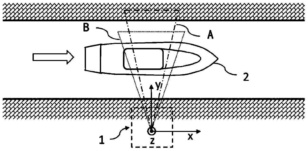
[0031] figure 1 It is a working schematic diagram of the ship height measuring device according to the embodiment of the present invention. Such as figure 1 As shown, the ship height measuring device 1 is installed on the shore, for example, when the ship 2 passes near the ship height measuring...


PUM


Abstract

The invention discloses a ship height measuring method and device. The method comprises steps of usingfirst laser three-dimensional scanning device and a camera which have a known relative pose relation for obtaining three-dimensional data and a two-dimensional image of a ship body respectively; finding a detection highest point of the ship body as a ship body height initial value based on the three-dimensional data; mapping part of the three-dimensional data into the two-dimensional image to obtain corresponding two-dimensional coordinates and height values; and correcting the initial ship body height value based on the two-dimensional image and the two-dimensional coordinates and height values corresponding to the partial three-dimensional data. According to the invention, on one hand, the advantages of high single-point measurement precision and small environmental influence of the laser three-dimensional scanning device are utilized, and on the other hand, the result obtained by laser scanning measurement is corrected by utilizing the two-dimensional image, so that the measurement accuracy is further improved.

Description

technical field [0001] The invention relates to a three-dimensional measurement technology, in particular to a ship measurement method and device based on laser three-dimensional scanning technology. Background technique [0002] When a ship passes through a lock or bridge, in order to avoid collision accidents due to the height of the ship or the container it carries, it is necessary to measure the height of the ship by remote sensing. Most of the existing ship height measurement adopts image processing technology, and the camera is used to shoot the ship, and then the ship height is obtained by processing the captured image. However, the shooting of the camera is greatly affected by the environment, and the acquisition of 3D information based on image processing requires the system to have a large data computing capability, which causes certain limitations. [0003] To this end, people have explored and developed ship height measurement technology based on lidar. For exa...

Claims


Application Information

Patent Timeline
IPC IPC(8): G01B11/06
CPCG01B11/0608G01B11/0691
Inventor 李沛林姜璐
Owner BEIJING UPHOTON OPTOELECTRONICS DEV CO LTD
Learn More