Method, device and system for testing circuit board of electronic lock
A test method and circuit board technology, applied in the direction of electronic circuit testing, measuring devices, measuring electricity, etc., can solve problems such as inability to test digital keys, and achieve the effects of improving test efficiency, ensuring accuracy and stability, and improving production quality
- Summary
- Abstract
- Description
- Claims
- Application Information
AI Technical Summary
Problems solved by technology
Method used
Image
Examples
Embodiment 1
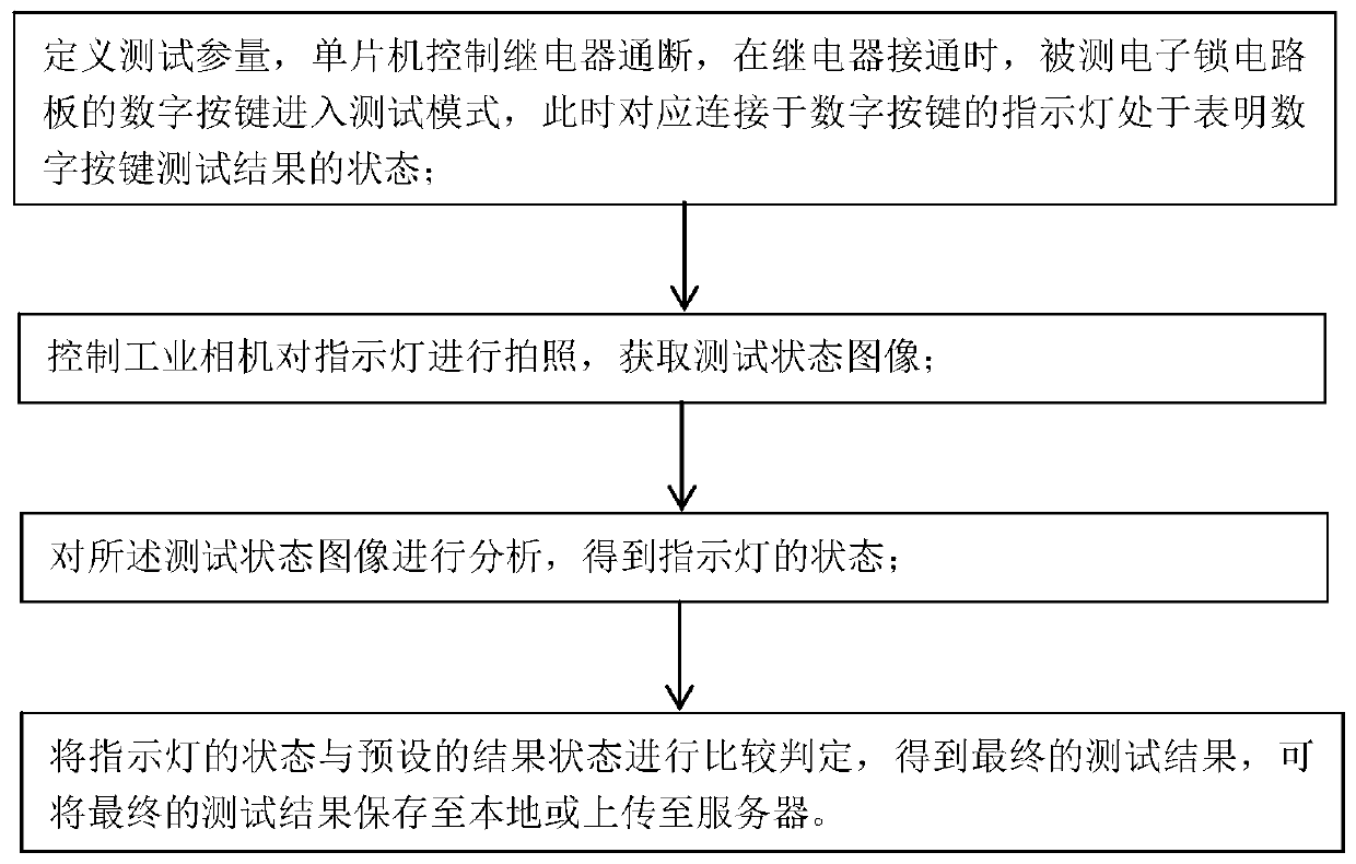
[0045] This embodiment provides a method for testing an electronic lock circuit board, which is used on a host computer, such as figure 2 shown, including:
[0046] S1. Define the test parameters, and control the on-off of the relay through the single-chip microcomputer according to the defined test parameters. When the relay is turned on, the digital keys of the electronic lock circuit board under test enter the test mode and test one by one. At this time, the corresponding keys connected to the digital The indicator light of the button is in the state showing the test result of the digital button, and in a specific embodiment, the indicator light can be located on the upper half of the circuit board under test, and there are only two indicator lights, red and blue;
[0047]S2. Control the industrial camera to take pictures of the indicator light to obtain the test status image; the number of pictures taken and the frequency of the pictures are different for different test i...
Embodiment 2
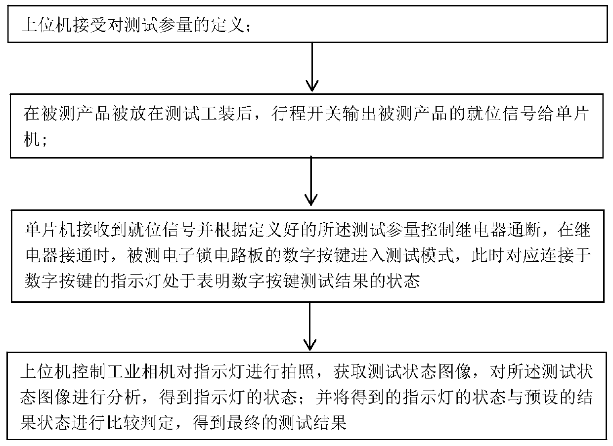
[0058] This embodiment provides a method for testing electronic lock circuit boards, such as image 3 shown, including:
[0059] (1), the upper computer accepts the definition of the test parameters;
[0060] (2) After the product under test is placed on the test tool, the limit switch outputs the in-position signal of the product under test to the microcontroller,
[0061] (3), the single-chip microcomputer receives the in-position signal and controls the on-off of the relay according to the defined test parameters. When the relay is turned on, the digital keys of the electronic lock circuit board under test enter the test mode, which is correspondingly connected to the digital keys at this time. The indicator light of the button is in the state of indicating the test result of the number key;
[0062] (4), the host computer controls the industrial camera to take pictures of the indicator light, obtains the test state image, analyzes the test state image, and obtains the st...
Embodiment 3
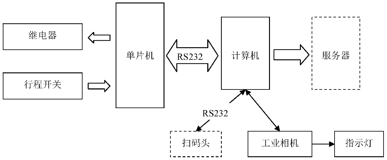
[0067] In this embodiment, an electronic lock circuit board testing device is provided, which is used on a host computer, such as Figure 4 shown, including:
[0068] The definition module is used to accept the definition of the test parameters, and control the on-off of the relay through the single-chip microcomputer according to the defined test parameters. When the relay is turned on, the digital keys of the electronic lock circuit board under test enter the test mode. The indicator light of the number key is in the state of indicating the test result of the number key;
[0069] The control module is used to control the industrial camera to take pictures of the indicator light and obtain the test status image;
[0070] An image analysis module, configured to analyze the test state image to obtain the state of the indicator light;
[0071] The comparison and judgment module compares and judges the state of the indicator light with the preset result state to obtain the fina...
PUM
 Abstract
Description
Claims
Application Information
 - R&D
- Intellectual Property
- Life Sciences
- Materials
- Tech Scout
- Unparalleled Data Quality
- Higher Quality Content
- 60% Fewer Hallucinations
Browse by: Latest US Patents, China's latest patents, Technical Efficacy Thesaurus, Application Domain, Technology Topic, Popular Technical Reports.
© 2025 PatSnap. All rights reserved.Legal|Privacy policy|Modern Slavery Act Transparency Statement|Sitemap|About US| Contact US: help@patsnap.com


