
Movable platform

A mobile platform and stage technology, applied in the field of medical devices, can solve the problems of imaging depth limit, inability to image, optical imaging resolution limit, etc., and achieve the effect of efficient and fast acquisition, time saving and accurate acquisition

Inactive Publication Date: 2020-06-05
江苏迪赛特医疗科技有限公司
View PDF0 Cites 1 Cited by
  • Summary
  • Abstract
  • Description
  • Claims
  • Application Information

AI Technical Summary

Problems solved by technology

The first problem is the resolution limit of optical imaging, often called "Abbe limit", for visible light imaging, this value is 200nm
The second problem is the field of view limit at high resolution, that is to say, the more you want to see a small target, the smaller the field of view
The third problem is the imaging depth limit. For high-resolution optical imaging, there is a "soft limit" of 1mm. For example, the penetration depth of confocal microscope is only about 0.5mm
[0004] Considering the limitations of the imaging field of view and imaging depth, it is impossible to use an optical microscope alone to image a large sample completely

Method used


Image

  • Movable platform
  • Movable platform
  • Movable platform

Examples


Embodiment 1

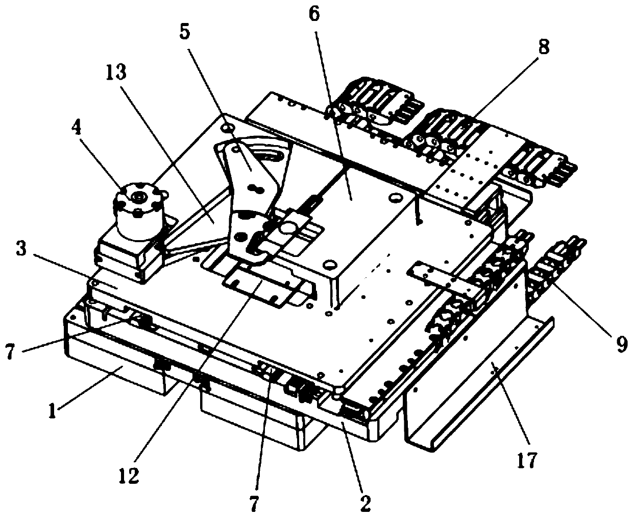
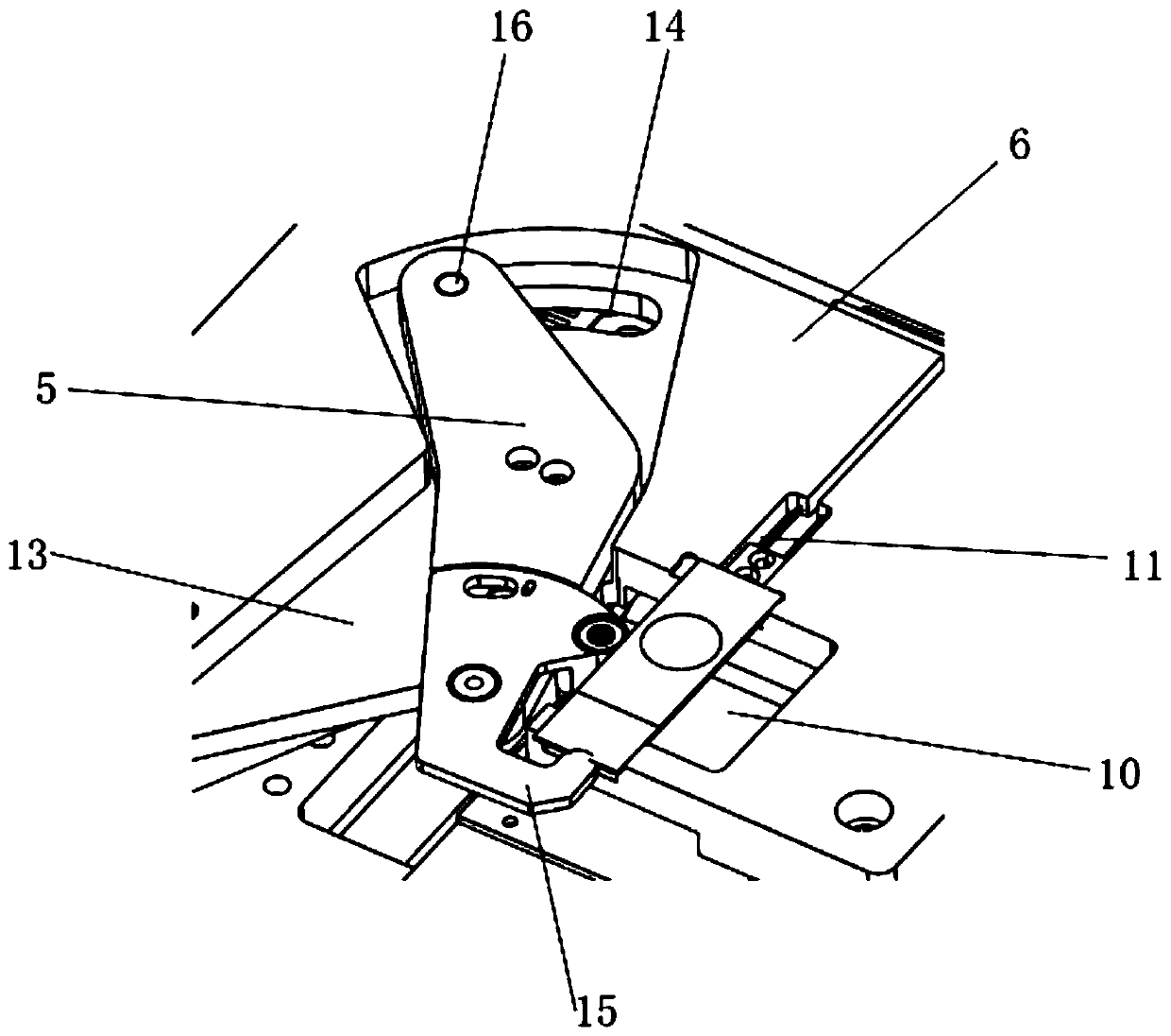
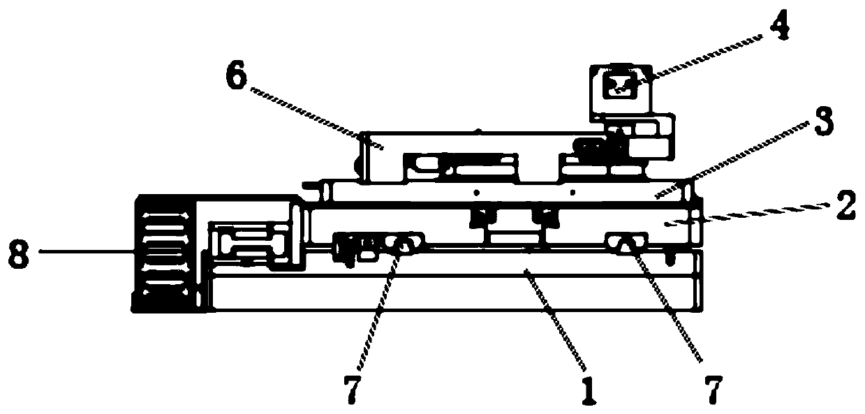
[0042] Embodiment 1 provides a kind of mobile platform, comprises base 1, X mobile platform 2, Y mobile platform 3, rotary cylinder 4, claw 5, support 6; Said base 1 and X mobile platform 2, Y mobile The platform 3 is arranged in parallel from bottom to top, and two guide rails 7 are arranged between the base 1 and the X mobile platform 2, and two guide rails 7 are arranged between the X mobile platform 2 and the Y mobile platform 3; the Y mobile platform 3 is provided with a support 6; the support 6 is provided with a rotary cylinder 4; the center of the hook 5 is connected to the rotating shaft arranged on the Y mobile platform 3, and is installed on the support 6;

[0043] The two guide rails 7 between the base 1 and the X mobile platform 2 and the two guide rails 7 between the X mobile platform 2 and the Y mobile platform 3 are vertically arranged at 90 degrees, and the guide rails are guide grooves and ball structures. There are ball limit pins at both ends of the groove;...


PUM


Abstract

The invention relates to the field of medical instruments, in particular to a movable platform. The movable platform comprises a base, an X moving platform, a Y moving platform, a rotating air cylinder, a claw and a support. The base, the X moving platform and the Y moving platform are arranged in parallel from bottom to top, two guide rails are arranged between the base and the X moving platform,and two guide rails are arranged between the X moving platform and the Y moving platform. The support is arranged on the Y moving platform. A rotary cylinder is arranged on the support. The center ofthe claw is connected with a rotating shaft arranged on the Y moving platform and is mounted on the bracket. By the adoption of the movable platform, the slide glass can be positioned, manual correction of an operator is not needed, accurate fixation can be achieved through the alignment air cylinder and the fixed check block, time is saved, and scanning efficiency is improved.

Description

technical field [0001] The present invention relates to the field of medical equipment, and more specifically relates to a movable platform. Background technique [0002] Optical microscope is the most important microscopic imaging technology. It is an optical instrument that uses optical principles to magnify and image tiny objects that cannot be resolved by the human eye, so that people can extract microstructure information. As early as the 1st century BC, people have discovered that when observing tiny objects through spherical transparent objects, they can be enlarged and imaged. In 1590, Dutch and Italian eyeglass makers had created magnifying instruments similar to microscopes. In the middle of the 17th century, both R. Hooke of England and A. van Levin Hooke of the Netherlands made outstanding contributions to the development of microscopes and started the development of modern microscopes. To this day, although ultra-precise microscopic techniques such as electron...

Claims


Application Information

Patent Timeline
Patent Type & Authority Applications(China)
IPC IPC(8): G02B21/26
CPCG02B21/26
Inventor 李文勇樊祥山陈巍王鹏蹇秀红殷亚娟陶军之高敏
Owner 江苏迪赛特医疗科技有限公司
Learn More