
Cross-road cable laying structure and construction method thereof

A cable laying and construction method technology, applied to overhead lines/cable equipment, cable suspension devices, etc., can solve the problems of time-consuming and labor-intensive, cable slump, unstable cable installation structure, etc., to reduce looseness and shedding, and improve construction. Efficiency, clean and controllable installation structure

Inactive Publication Date: 2020-06-05
河南华能联合电力建设有限公司
View PDF3 Cites 2 Cited by
  • Summary
  • Abstract
  • Description
  • Claims
  • Application Information

AI Technical Summary

Problems solved by technology

[0003] In the existing cable laying process, in order to reduce the long-term traffic interruption caused by construction, the poles are usually erected temporarily. The cable installation structure is extremely unstable, and it is easy to be affected by the climate and environment to cause the cable to collapse. It needs to be repaired many times in the follow-up, which is time-consuming and labor-intensive, so it needs to be improved

Method used


Image

  • Cross-road cable laying structure and construction method thereof
  • Cross-road cable laying structure and construction method thereof
  • Cross-road cable laying structure and construction method thereof

Examples


Embodiment Construction

[0046] The present invention will be described in further detail below in conjunction with the accompanying drawings.

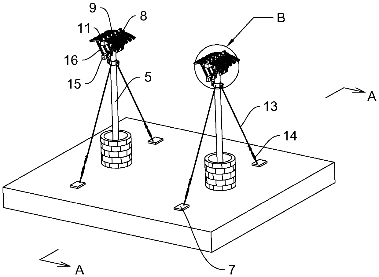
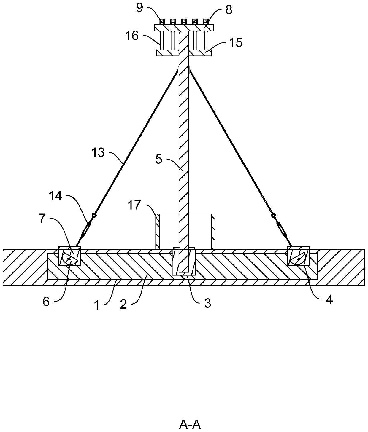
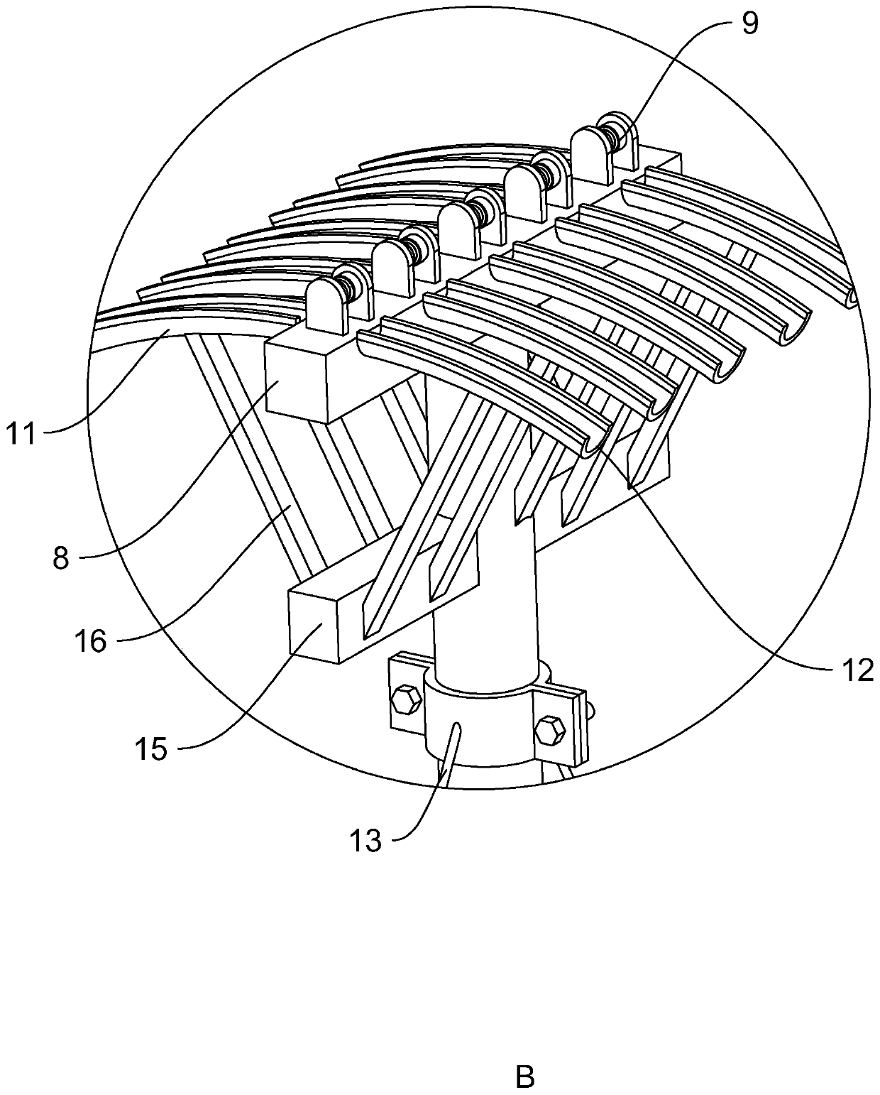
[0047] refer to figure 1 and figure 2 , is a cross-road cable laying structure disclosed by the present invention, including pre-embedded pits 1 respectively opened in the soil on both sides of the road, pre-embedded bases 2 are pre-embedded in the pre-embedded pits 1, and the pre-embedded bases 2 are made of concrete Prefabricated with steel bars, the depth of the pre-embedded pit 1 is greater than the height of the pre-embedded base 2, and the sides of the pre-embedded base 2 are filled with soil layers. The prefabricated pre-embedded base 2 is used as the base to form a stable support connection structure in the soil body, which is easy to produce, environmentally friendly, convenient to construct, and low in cost.

[0048]The pre-embedded base 2 is provided with a pole installation pit 3 and a pull plate installation pit 4, a cable pole 5 is installed ...


PUM


Abstract

The invention relates to a cross-road cable laying structure and a construction method thereof, which relate to the technical field of power engineering construction, and solve the problem that the temporarily-built vertical rods tension the wires off the ground easily, so that a cable mounting structure is extremely unstable. The cross-road cable laying structure comprises the pre-buried pits formed in the soil bodies at the two sides of a road respectively, pre-buried bases are pre-buried in the pre-buried pits, supporting rod mounting pits and pull disc mounting pits are formed in the pre-buried bases, and the cross-road cable laying structure further comprises cable supporting rods, pull disc blocks, reinforcing bodies, transverse rods, pulleys, arch-shaped guide pipes, guide grooves,pull wires and pull rods. The method comprises the steps of S1 prefabricating the pre-buried bases, the cable supporting rods and the pull disc blocks; S2 arranging the pre-buried pits; S3 burying thepre-buried bases in the pre-buried pits; S4, connecting the pull wires, the cable vertical rods, the pull rods and the pull disc blocks; S7 piling the protective piles; S8, erecting the cable. The cross-road cable laying structure is stable in structure and short in construction period, and is firm, durable and environment friendly.

Description

technical field [0001] The invention relates to the technical field of electric power engineering construction, in particular to a cross-road cable laying structure and a construction method thereof. Background technique [0002] Power cables are used to transmit and distribute high-power electric energy. Usually, factory power is connected from 10KV high-voltage wires, and then transmitted to the high-voltage cabinet as the incoming power supply through high-voltage cables. In power installation projects, cables are often involved. For laying problems, common cable laying methods include buried laying, bracket laying, pipe jacking laying, bridge laying, etc. In the construction of power cable laying, ensuring the safety of cable laying, structural stability, and less post-repair is the key point in construction. [0003] In the existing cable laying process, in order to reduce the long-term traffic interruption caused by construction, the poles are usually erected temporari...

Claims


Application Information

Patent Timeline
Patent Type & Authority Applications(China)
IPC IPC(8): H02G1/04H02G7/05
CPCH02G1/04H02G7/05
Inventor 燕展苏晨阳刘艳涛
Owner 河南华能联合电力建设有限公司
Learn More