
Remote control method and system for laser cutting equipment

A remote control system and laser cutting technology, applied in laser welding equipment, general control system, control/adjustment system, etc., can solve the problems affecting the processing process, the processing process cannot be continued, and the customer service end and the equipment end cannot be satisfied. Realize the effect of data transmission

Pending Publication Date: 2020-06-05
JINAN BODOR LASER CO LTD
View PDF6 Cites 2 Cited by
  • Summary
  • Abstract
  • Description
  • Claims
  • Application Information

AI Technical Summary

Problems solved by technology

It cannot meet the situation that the three operations of intranet penetration, remote control, and data transmission between the customer service end and the device end exist at the same time
[0004] Moreover, the laser cutting equipment can continue to work according to the preset parameters and processes, and communicate with the server. In the prior art, if the network communication is disconnected, the laser cutting equipment cannot receive control instructions in real time, which will cause the processing process to fail and affect the processing. process

Method used


Image

  • Remote control method and system for laser cutting equipment
  • Remote control method and system for laser cutting equipment
  • Remote control method and system for laser cutting equipment

Examples


Embodiment Construction

[0054] Those of ordinary skill in the art can realize that the units and algorithm steps of the examples described in conjunction with the embodiments disclosed herein can be implemented by electronic hardware, computer software, or a combination of the two. In order to clearly illustrate the relationship between hardware and software Interchangeability. In the above description, the composition and steps of each example have been generally described according to their functions. Whether these functions are executed by hardware or software depends on the specific application and design constraints of the technical solution. Skilled artisans may use different methods to implement the described functions for each specific application, but such implementation should not be regarded as exceeding the scope of the present invention.

[0055] The block diagrams shown in the drawings are merely functional entities and do not necessarily correspond to physically separate entities. Tha...


PUM


Abstract

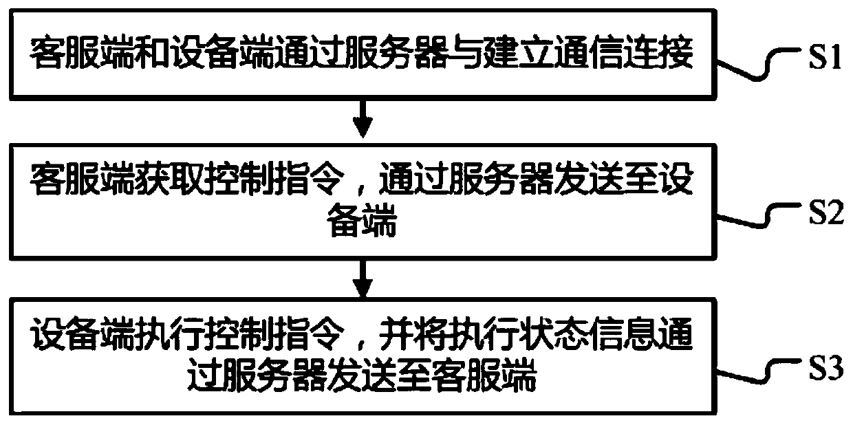
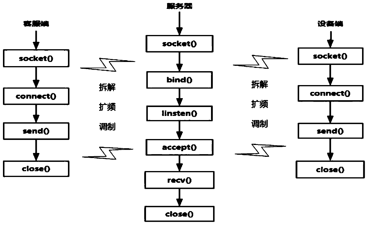
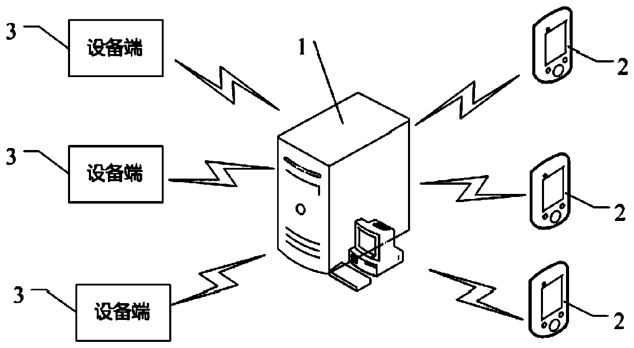
The invention provides a remote control method and system for laser cutting equipment. A customer service terminal and an equipment terminal establish communication connection through a server; the customer service terminal obtains the control instruction and sends the control instruction to the equipment terminal through the server; and the equipment side executes the control instruction and sends the execution state information to the customer service side through the server; the customer service terminal and the equipment terminal log in the server based on the unique information, and whenthe client and the equipment terminal are in network communication connection, the server helps to find the target terminal to transmit the information; the customer service terminal generates a control instruction according to the help request and sends the control instruction to the equipment terminal through the server to request the remote control equipment so as to realize operation control of the laser equipment, data setting and equipment debugging. The customer service terminal generates data transmission and realizes data transmission of the laser equipment through the server; when the equipment side generates feedback, the feedback can be forwarded to the customer service side through the server, effectively realizing the data transmission between the customer service end and theequipment end.

Description

technical field [0001] The present invention relates to the technical field of laser cutting equipment, in particular to a remote control method and system for laser cutting equipment. Background technique [0002] Laser cutting equipment is based on focusing the emitted laser light into a high-density laser beam, which is then emitted to the workpiece to be processed for cutting operations. [0003] Laser cutting equipment has begun to adopt automatic control, and the operator inputs the corresponding process parameters through the control terminal, which is automatically executed by the equipment. In the existing technology, cloud services are usually integrated into the remote control of laser cutting equipment to achieve high-speed delivery of applications in the cloud, including an overall access method and a "request-response" path for applications View end-to-end. It cannot meet the situation that the three operations of intranet penetration, remote control, and dat...

Claims


Application Information

Patent Timeline
IPC IPC(8): H04L29/08H04L29/06H04L29/12G05B19/406B23K26/38
CPCH04L67/141H04L67/145H04L67/125H04L69/162H04L61/255G05B19/406B23K26/38
Inventor 孔文一董立洋
Owner JINAN BODOR LASER CO LTD
Learn More