Vibration exciter

A vibration exciter and excitation technology, applied in the direction of fluid using vibration, etc., can solve the problems of easy burning of electrical components, increase of current of excitation motor, poor adjustment accuracy, etc.

Pending Publication Date: 2020-06-09
JINAN HAOTE INNOVATION MANAGEMENT & CONSULTING PARTNERSHIP LLP
View PDF0 Cites 1 Cited by
  • Summary
  • Abstract
  • Description
  • Claims
  • Application Information

AI Technical Summary

Problems solved by technology

In addition, the adjustment accuracy is poor. It is difficult to adjust the eccentricity to achieve the optimal excitation force parameter during work. It can only be "close" or "almost", and it is impossible to dynamically adjust the excitation force during work.
Another disadvantage of the traditional vibrator is th

Method used


Image

  • Vibration exciter
  • Vibration exciter
  • Vibration exciter

Examples


Embodiment 1

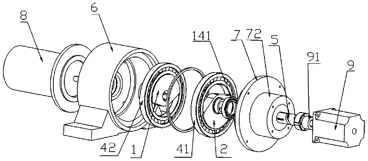
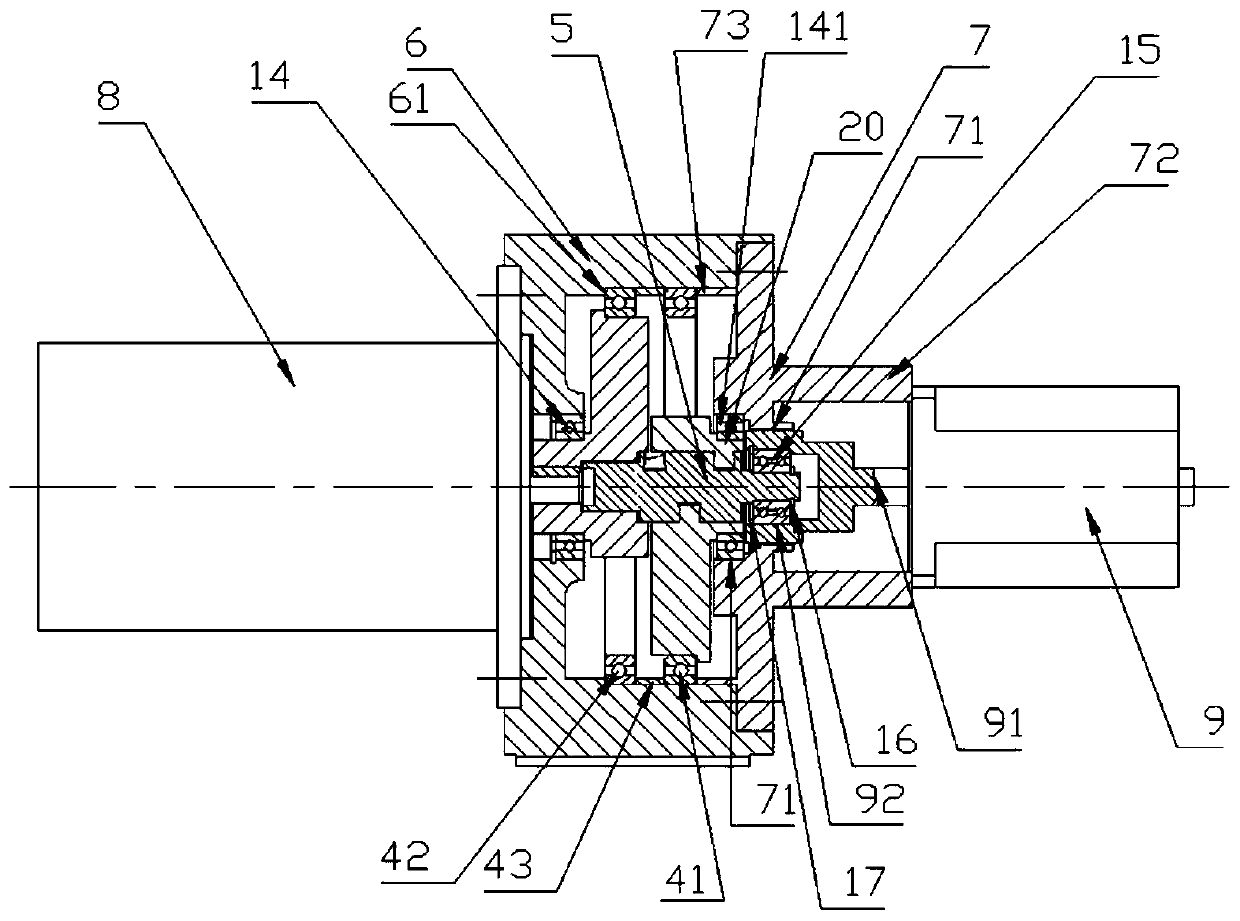
[0069] Such as figure 1 , figure 2 As shown, an exciter includes an eccentric vibrator, an excitation box 6 for accommodating the eccentric vibrator, an excitation motor 8 for driving the eccentric vibrator to rotate, and a servo linear motion system for adjusting the eccentricity of the eccentric vibrator 9. The eccentric vibrator includes a first eccentric body 1 , a second eccentric body 2 and a connecting shaft 5 . The first eccentric body 1 and the second eccentric body 2 are arranged side by side in the left and right directions, the first eccentric body 1 is a left eccentric body, the second eccentric body 2 is a right eccentric body, and the second eccentric body 2 and the center of gravity of the first eccentric body 1 deviate from the center of rotation formed by the connecting shaft 5 .

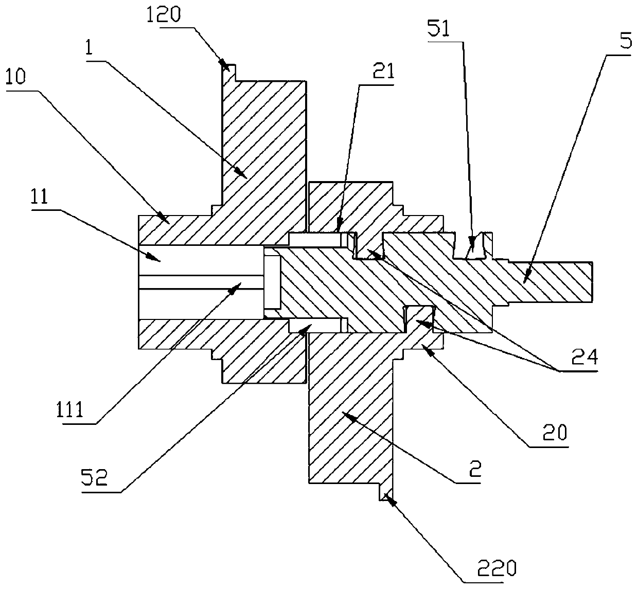
[0070] Such as image 3 As shown, the first eccentric body 1 is provided with a left pillow block 10 , and the left pillow block 10 is provided with a first shaft hole 11 . T...

Embodiment 2

[0081] Same as Embodiment 1, except that a second linear groove is set in the first shaft hole 11

[0082] The left side of the connecting shaft 5 is provided with a third boss that matches the second linear groove; the second helical groove is provided in the second shaft hole 2, and the right side of the connecting shaft 5 is provided with a The fourth boss matched with the second helical groove.

[0083] There are two third bosses, which are arranged on the trajectory line matched with the second linear groove; there are two fourth bosses, which are arranged on the trajectory line matched with the second helical groove superior.

Embodiment 3

[0085] It is the same as Embodiment 1, except that this embodiment provides another specific connection method between the servo linear motion system 9 and the connecting shaft 5 . Such as Figure 4 As shown, the servo linear motion system 9 is provided with a servo linear motion system seat 13, and the servo linear motion system seat 13 is fixedly connected with the vibration excitation box cover 7; the vibration excitation box cover through hole 71 is located in the The center position where the vibration box cover 7 is connected to the servo linear motion system seat 13 . The servo linear motion system seat 13 is provided with a servo linear motion system seat through hole 131, and the servo linear motion system actuator 91 of the servo linear motion system 9 passes through the servo linear motion system seat through hole 131 and contacts with the servo linear motion system seat. One end of the connecting shaft 5 is connected through a fifth bearing 15 .


PUM


Abstract

The invention discloses a vibration exciter, and belongs to the technical field of vibration machinery. The vibration exciter comprises an eccentric vibrator, a vibration excitation box (6) for accommodating the eccentric vibrator, a vibration excitation motor (8) for driving the eccentric vibrator to rotate and further a servo linear motion system (9) for adjusting eccentricity of the eccentric vibrator; and the eccentric vibrator at least comprises a first eccentric body (1), a second eccentric body (2) and a connecting shaft (5), wherein at least one of the first eccentric body (1) and thesecond eccentric body (2) is connected with the connecting shaft (5) through a spiral groove and a boss structure matched with the spiral groove, and the servo linear motion system (9) is connected with the connecting shaft (5). The vibration exciter can adjust the magnitude of exciting force at a static state or any rotating speed.

Description

technical field [0001] The invention belongs to the technical field of vibration machinery, and in particular relates to an exciter installed on vibration machinery equipment. Background technique [0002] The exciter is a device installed on the vibration mechanical equipment to generate the exciting force. It is the main component of the vibration machine and plays a decisive role in the vibration mode of the machine. Vibrating machines equipped with exciters are widely used in metallurgical mines, industrial production, engineering construction, and experimental equipment to achieve screening, transportation, compaction, vibration aging, and forming of objects. At present, the existing mechanical exciter is mainly composed of a motor and an eccentric vibrator, and the motor drives the movement of the eccentric vibrator to generate mechanical vibration. This kind of vibrator can only control the vibration frequency by controlling the rotating speed of the vibrating motor,...

Claims


Application Information

Patent Timeline
IPC IPC(8): B06B1/16
CPCB06B1/164
Inventor 王阳刘秀娟赵志明
Owner JINAN HAOTE INNOVATION MANAGEMENT & CONSULTING PARTNERSHIP LLP
Why Eureka
Try Eureka