
Metal plate machining chamfering equipment

A sheet metal and corner technology, applied in the field of sheet metal processing chamfering equipment, can solve the problems of insecurity, uneven sides of sheet metal raw materials, and easy scratching of air-conditioning rack accessories, so as to improve accuracy, Process continuous and efficient, quality-assured effects

Pending Publication Date: 2020-06-09
谢秀林
View PDF0 Cites 0 Cited by
  • Summary
  • Abstract
  • Description
  • Claims
  • Application Information

AI Technical Summary

Problems solved by technology

[0002] When producing air-conditioning racks, it is necessary to use sheet metal processing equipment. The sheet metal processing equipment will straighten and punch the rolled sheet metal to form air-conditioning rack accessories. The two sides of the sheet metal were not chamfered during the sheet metal process, resulting in the production of air-conditioning rack accessories that are easy to scratch and unsafe. Therefore, it is urgent to design a continuous, efficient, and accurate sheet metal processing chamfering equipment

Method used


Image

  • Metal plate machining chamfering equipment
  • Metal plate machining chamfering equipment
  • Metal plate machining chamfering equipment

Examples


Embodiment Construction

[0020] Embodiments of the technical solution of this embodiment will be described in detail below in conjunction with the accompanying drawings. The following embodiments are only used to illustrate the technical solution of this embodiment more clearly, so they are only examples, and should not be used to limit the protection scope of this embodiment.

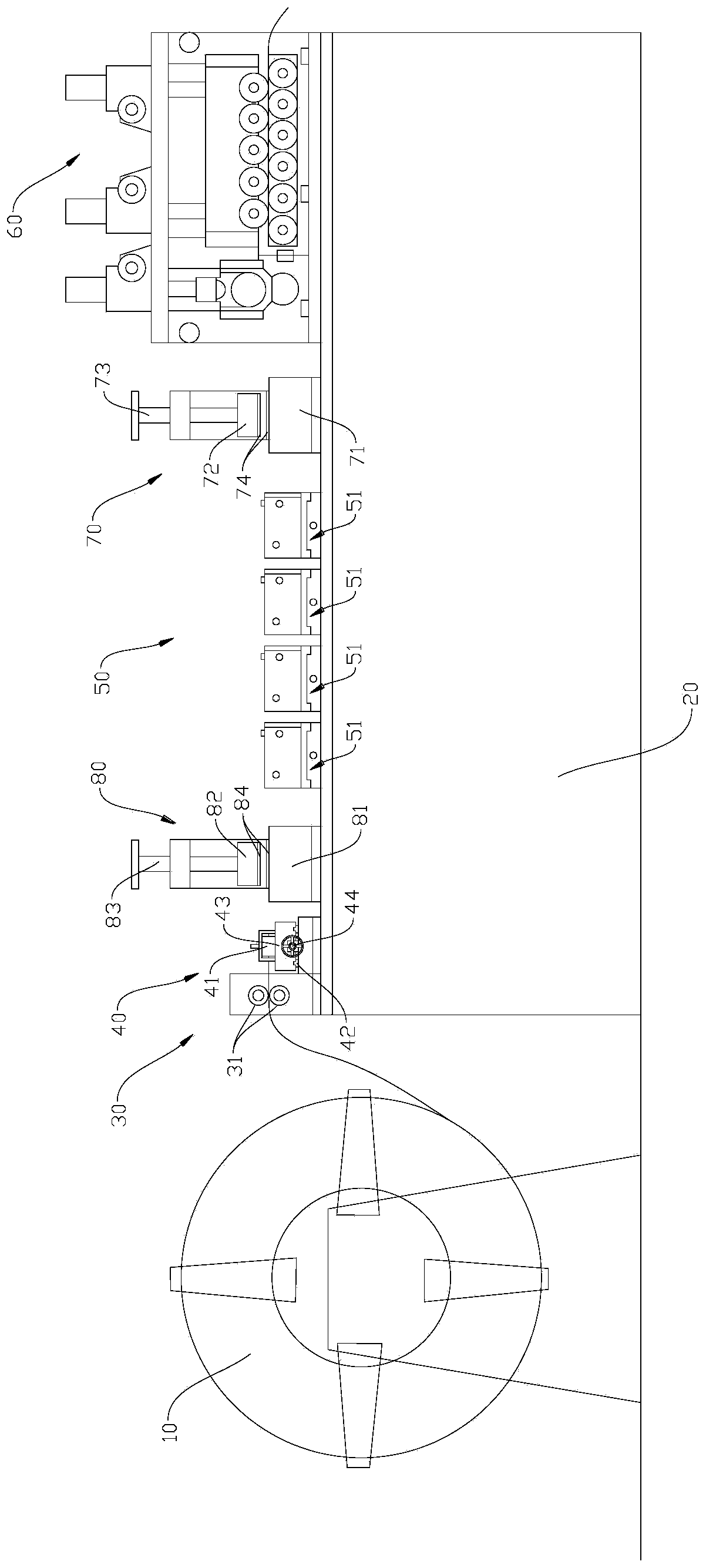
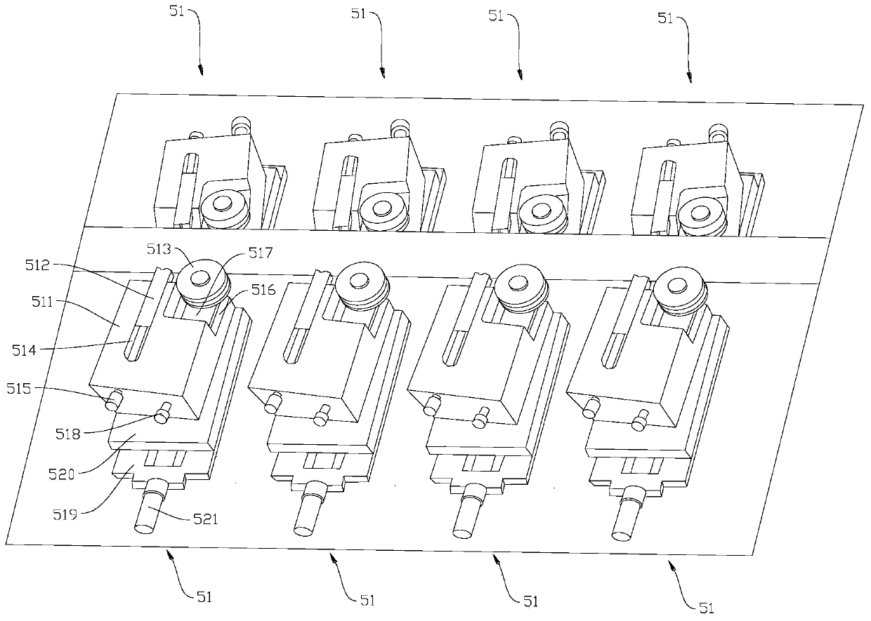
[0021] Such as Figure 1-Figure 3 As shown, the embodiment of the present invention provides a sheet metal processing chamfering equipment, including a discharge rack 10 and a frame 20, the discharge frame 10 leads the sheet metal to the frame 20, and the frame 20 is sequentially provided with an introduction mechanism 30. A limit mechanism 40, a chamfering mechanism 50 and a pulling mechanism 60 for pulling sheet metal.

[0022] The introduction mechanism 30 includes a pair of flat nip rollers 31 respectively clamped on the upper and lower sides of the sheet metal. The limit mechanism 40 includes a pair of first limit wheel...


PUM


Abstract

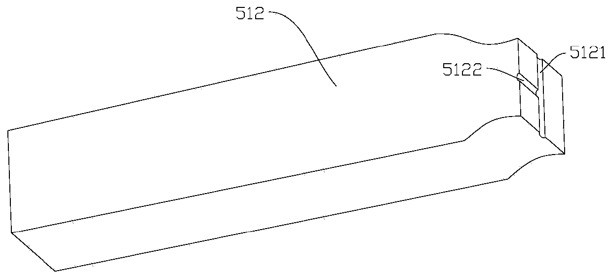
The invention discloses metal plate machining chamfering equipment. The metal plate machining chamfering equipment comprises a discharging frame and a rack, a metal plate is led out to the rack through the discharging frame, and a lead-in mechanism, a limiting mechanism, a chamfering mechanism and a traction mechanism used for dragging the metal plate are sequentially arranged on the rack; the lead-in mechanism comprises a pair of flat clamping rollers which are clamped on the upper side and the lower side of the metal plate; the limiting mechanism comprises a pair of first limiting wheels clamped to the left side and the right side of the metal plate correspondingly; the chamfering mechanism comprises at least one pair of cutting assemblies symmetrically arranged on the two sides of the metal plate, each cutting assembly comprises a tool apron, a tool bit and a second limiting wheel, the tool aprons are installed on the rack, the tool bits are installed on the tool aprons, and the blade ends of the tool bits abut against the side edges of the metal plate to be used for cutting and chamfering of the side edges of the metal plate; and the second limiting wheels are arranged in frontof the tool bits and installed on the tool aprons, and the second limiting wheels abut against the side edges of the metal plate. According to the metal plate machining chamfering equipment, the sideedges of the metal plate can be chamfered continuously, efficiently and accurately.

Description

technical field [0001] The invention relates to the technical field of sheet metal processing equipment, in particular to a sheet metal processing chamfering equipment. Background technique [0002] When producing air-conditioning racks, it is necessary to use sheet metal processing equipment. The sheet metal processing equipment will straighten and punch the rolled sheet metal to form air-conditioning rack accessories. The two sides of the sheet metal were not chamfered during the sheet metal process, resulting in the production of air-conditioning rack accessories that are easy to scratch and unsafe. Therefore, it is urgent to design a continuous, efficient, and accurate sheet metal processing chamfering equipment. Contents of the invention [0003] Aiming at the defects in the prior art, the present invention provides a sheet metal processing chamfering equipment to continuously, efficiently and accurately chamfer the sides of the sheet metal. [0004] The invention pr...

Claims


Application Information

Patent Timeline
IPC IPC(8): B23D79/00B23Q3/06B23Q5/22B23Q11/10B23Q11/00
CPCB23D79/00B23Q3/06B23Q5/22B23Q11/0042B23Q11/10
Inventor 谢秀林
Owner 谢秀林
Learn More