Joint of steel pipe concrete column and cast-in-place reinforced concrete beam and construction method of joint

A technology for reinforced concrete beams and CFST columns, which is applied to the joints of CFST columns and cast-in-place reinforced concrete beams and their construction fields, can solve the problems of low connection reliability, stress deformation at the welded part of the steel pipe columns, and low bearing capacity of nodes. , to achieve the effect of convenient operation

Active Publication Date: 2020-06-09
湖南省西城建设有限公司
View PDF22 Cites 9 Cited by
  • Summary
  • Abstract
  • Description
  • Claims
  • Application Information

AI Technical Summary

Problems solved by technology

[0004] The above-mentioned existing technical solutions have the following defects. Since the pipe wall of the steel pipe column is relatively thin, the H-shaped steel end is directly welded on the pipe wall of the steel pipe column, which will easily cause stress deformation at the welded part of the steel pipe column, and the connection reliability is low. , resulting in a lower bearing capacity of the node

Method used


Image

  • Joint of steel pipe concrete column and cast-in-place reinforced concrete beam and construction method of joint
  • Joint of steel pipe concrete column and cast-in-place reinforced concrete beam and construction method of joint
  • Joint of steel pipe concrete column and cast-in-place reinforced concrete beam and construction method of joint

Examples


Embodiment 1

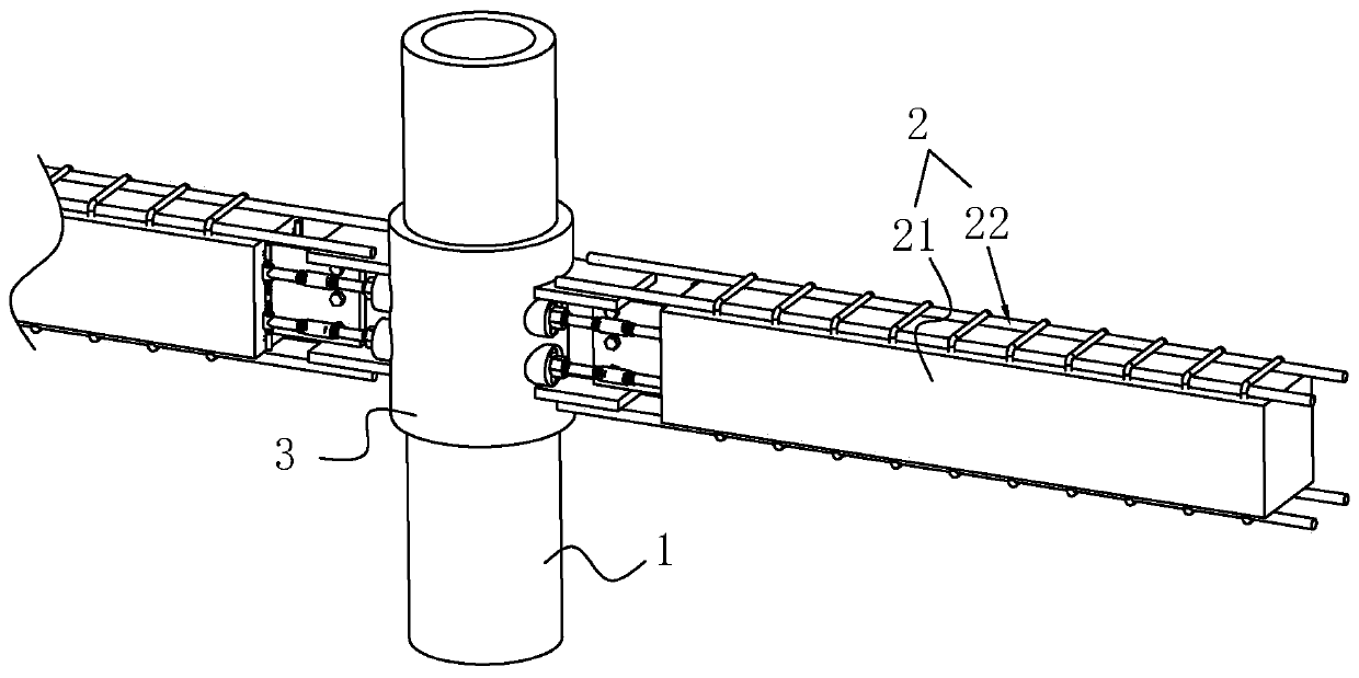
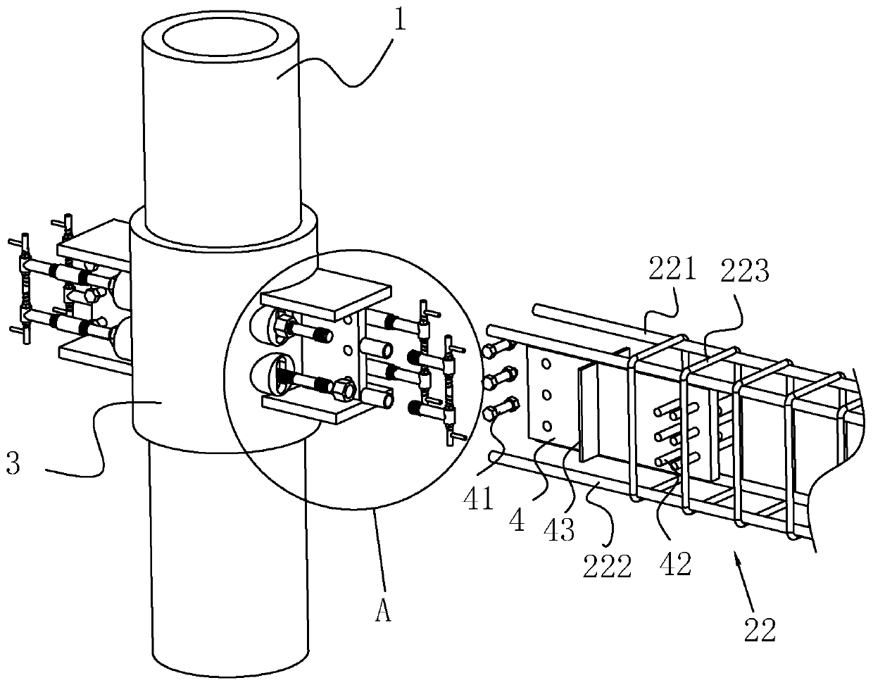
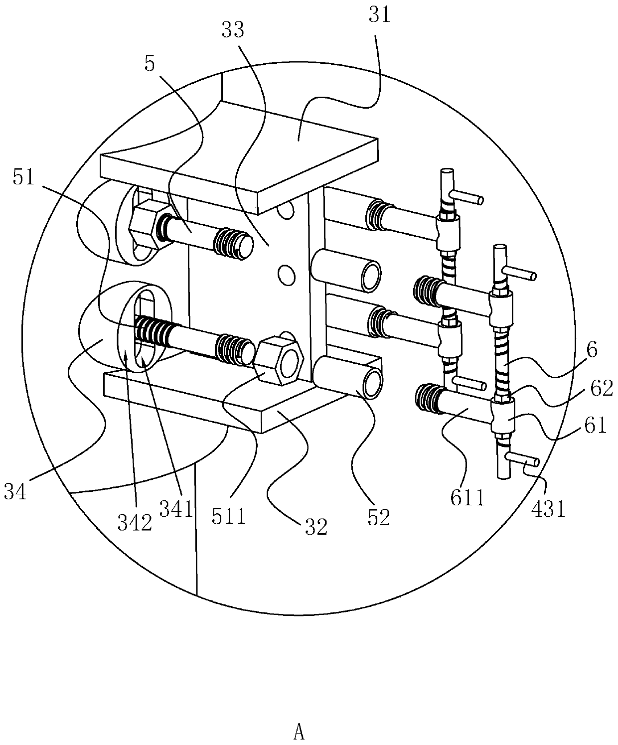
[0041] like figure 1 , 2 As shown, a joint between a steel pipe concrete column and a cast-in-place reinforced concrete beam includes a steel pipe column 1 and a concrete beam 2, and also includes a casing 3 fixedly sleeved on the steel pipe column 1, and the casing 3 is made of steel. The steel pipe column 1 is provided with steel bars and poured with concrete. An upper cover plate 31 and a lower cover plate 32 are fixedly arranged on the sleeve pipe 3, and a connection plate 33 is fixedly arranged on the sleeve pipe 3. The connection plate 33 is located between the upper cover plate 31 and the lower cover plate 32, and the two ends of the connection plate 33 Welded with the upper cover plate 31 and the lower cover plate 32 respectively;

[0042] like figure 2 , 3 As shown, the concrete beam 2 includes a concrete structure 21 and a reinforcement cage 22. The reinforcement cage 22 includes an upper main reinforcement 221, a lower main reinforcement 222 and a stirrup 223. ...

Embodiment 2

[0055] S1, mark the installation position of the casing 3 on the reinforcement column;

[0056] S2. Set the casing 3 at the position marked on the reinforcement column, and fix the location of the casing 3;

[0057] S3. Install the connecting rod 5, insert the connecting rod 5 into the casing 3 and the steel pipe column 1, and adjust the position of the connecting rod 5 so that the lengths of the two ends of the connecting rod 5 protruding from the casing 3 are equal, and tighten the limit nut 511 ;

[0058] S4, install the reinforcement cage 22, connect the connecting plate 33 with the embedded plate 4 through the connecting bolt 41, weld the upper main rib 221 on the upper cover plate 31, and weld the lower main rib 222 on the lower cover plate 32;

[0059] S5. Pour concrete into the reinforcement cage 22 to form the concrete beam 2 .


PUM


Abstract

The invention relates to a joint of a steel pipe concrete column and a cast-in-place reinforced concrete beam and a construction method of the joint and belongs to the technical field of building structures. The joint comprises a steel pipe column and a concrete beam and also comprises a casing pipe fixedly arranged on the steel pipe column in a sleeving manner, an upper cover plate and a lower cover plate are fixedly arranged on the casing pipe, a connecting plate is fixedly arranged on the casing pipe, and the connecting plate is located between the upper cover plate and the lower cover plate; a pre-buried plate is fixedly arranged in the concrete beam; a connecting rod vertical to the steel pipe column is arranged in the steel pipe column in a penetrating manner, two ends of the connecting rod penetrate the casing pipe, a through hole where the connecting rod penetrates is formed in the casing pipe, the connecting rod is parallel to the concrete beam, and the connecting rod is fixedly connected to the concrete beam. The connecting rod plays a role of positioning the casing pipe to prevent displacement of the casing pipe, so that the casing pipe is fixed conveniently. Meanwhile,the concrete beam and the steel pipe column are connected integrally, so that the reliability of integral connection is improved. The connecting rod is matched with the casing pipe, so that the reliability and the bearing capacity of integral connection are improved.

Description

technical field [0001] The invention relates to the technical field of building structures, in particular to a joint between a steel pipe concrete column and a cast-in-place reinforced concrete beam and a construction method thereof. Background technique [0002] Concrete-filled steel pipe column is a vertical load-bearing member of a composite structure formed by pouring concrete into steel pipes. It has high bearing capacity, good ductility, and convenient construction. It has been widely used in engineering. [0003] The Chinese patent application publication number CN108867889A discloses a connection node between a prefabricated reinforced concrete composite beam and a steel pipe column and its construction method, including a prefabricated steel pipe column, a prefabricated reinforced concrete composite beam, a U-shaped steel casing, a connection area and a composite steel pipe column. Plywood cast-in-place concrete; the prefabricated steel pipe column includes a steel ...

Claims


Application Information

Patent Timeline
Patent Type & Authority Applications(China)
IPC IPC(8): E04B1/58E04B1/30
CPCE04B1/185E04B1/30
Inventor 高展刘宏罗凡彭煚周志洋
Owner 湖南省西城建设有限公司
Why Eureka
Try Eureka