Precast wallboard molded with holes formed through steel mesh formworks

A prefabricated wallboard and steel mesh technology, applied to walls, structural elements, building components, etc., can solve the problems of inconvenient production, inconvenient flat mold production, high equipment and process requirements, and achieve the effect of convenient hole formation

Pending Publication Date: 2020-06-09
CABR TECH CO LTD
View PDF0 Cites 2 Cited by
  • Summary
  • Abstract
  • Description
  • Claims
  • Application Information

AI Technical Summary

Problems solved by technology

Among them, the production of double-sided laminated prefabricated wall panels generally adopts the flipping process, which has high requirements for equipment; the production of hollow prefabricated wall panels generally adopts the process of core-pulling to form holes or setting a removable inner mold to form holes, which requires more equipment and technology. It is high, and it is not convenient for flat mold production, and it is not convenient for the production of wallboards with various shapes and sizes
In addition, the common feature of the above-mentioned post-cast concrete lap joints is that there is a prefabricated and cast-in-place concrete joint surface between the vertical steel bars in the wall panel and the additional connecting steel bars in the cavity or hole, which is not conducive to lap joint force transmission.

Method used


Image

  • Precast wallboard molded with holes formed through steel mesh formworks
  • Precast wallboard molded with holes formed through steel mesh formworks
  • Precast wallboard molded with holes formed through steel mesh formworks

Examples


Embodiment 1

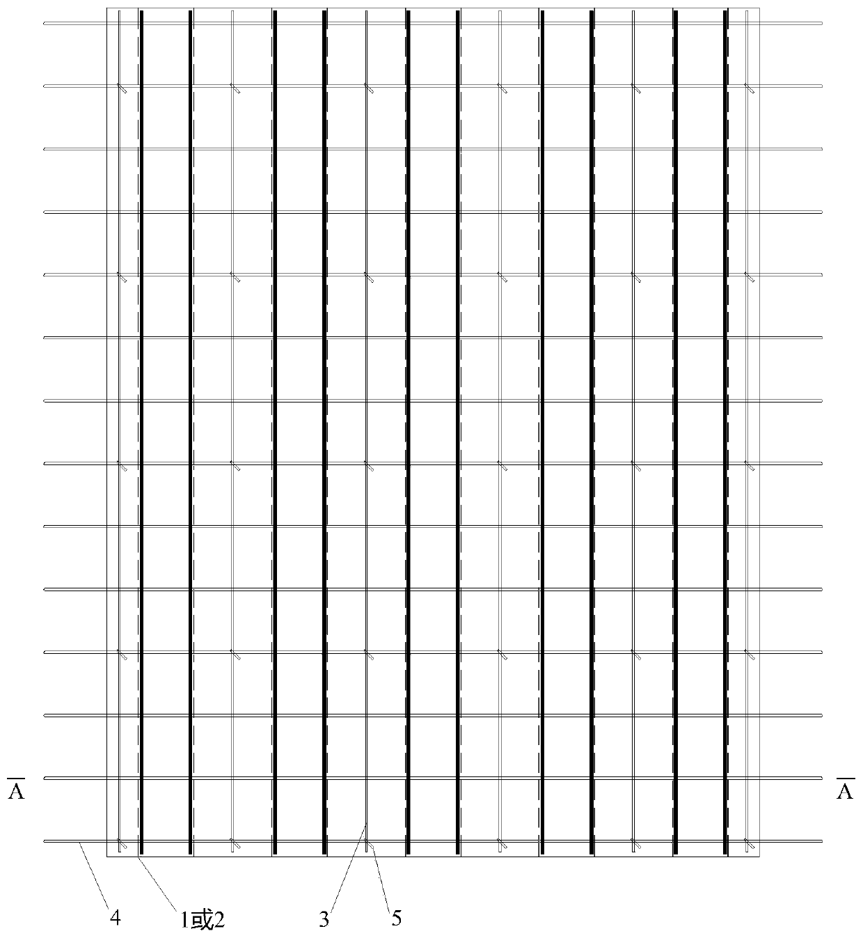
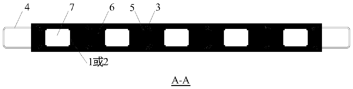
[0031] see figure 1 , figure 2 , is a structural schematic diagram of a prefabricated wall panel using a steel mesh mold to form holes in Example 1 of the present invention. There are no openings in the prefabricated wall panel, and the prefabricated wall panels are arranged at intervals (generally equidistant) Several steel mesh molds 1 or steel mesh molds 2 and vertical structural steel bars 3, horizontal steel bars 4 arranged at intervals along the vertical direction of the wall, structural tie bars 5 for connecting vertical structural steel bars 3 and horizontal steel bars 4, and The concrete 6 located outside each stencil form and poured in the factory, except the horizontal reinforcement 4 protruding from the wall, the rest of the components are located in the wall, wherein each stencil 1 or 2 respectively forms a vertical passageway in the wall. Long hole 7.

[0032] see image 3 , Figure 4 , the planar shape of the steel mesh mold 1 is a rectangle, and the steel ...

Embodiment 2

[0038] see Figure 8 , Figure 9 , is a structural schematic diagram of a prefabricated wall panel that adopts a steel mesh mold to form holes in Example 2 of the present invention. A hole 10 is provided in the prefabricated wall panel. Edge members 101 ( Figure 9 middle thick dotted line range), two steel mesh molds 1 are arranged at intervals in the range of each edge member 101, and these two steel mesh molds 1 form the vertical through-length hole 102 of the edge member, and the longitudinal reinforcement in the steel mesh mold 1 also To make the longitudinal reinforcement of the edge member, it is necessary to meet the cross-sectional area and bearing capacity requirements of the longitudinal reinforcement of the edge member; at the same time, the outside of the steel mesh formwork within the range of each edge member 101 also needs to set vertical structural steel bars 103 and tie bars 104, and the vertical structure of the set The diameter of steel bars 103 and tie b...


PUM

PropertyMeasurementUnit
Diameteraaaaaaaaaa
Sizeaaaaaaaaaa

Abstract

The invention discloses a prefabricated wallboard with holes formed through steel mesh formworks. The prefabricated wallboard is internally provided with vertical through-long holes, the holes are formed through the dismantling-free steel mesh formworks which are formed by welding longitudinal bars or angle steel, steel mesh and transverse keel during production of the wallboard, wherein the longitudinal bars or the angle steel in the steel mesh formworks serve as vertical stress reinforcing steel bars of a wall. No reinforcing steel bars stretch out of the prefabricated wallboard in the vertical direction, additional connecting reinforcing steel bars are arranged in the holes at the joint of the upper and lower layer wallboard, and concrete is poured into the holes to realize the lap joint connection of the vertical stress steel bars of the wall; and reinforcing steel bars stretch out of the prefabricated wallboard in the horizontal direction, and the same-layer adjacent wallboards are connected through a post-pouring section. The prefabricated wallboard is convenient to produce and construct, reasonable in connection structure, and capable of solving the problems that a traditional prefabricated wallboard is difficult to produce and construct, the lap joint transmission performance is difficult to guarantee, and the like.

Description

technical field [0001] The invention relates to the field of prefabricated components, in particular to a prefabricated wallboard, in particular to a prefabricated wallboard in which through-long holes are formed by arranging steel mesh molds welded by longitudinal bars or angle steels, steel meshes and transverse keels. Background technique [0002] At present, in my country's prefabricated concrete structure system, prefabricated wall panels have different structures according to the connection methods used. [0003] When the vertical reinforcement is connected by sleeve grouting or grouting anchor lap connection, the wall panels are generally fully prefabricated, and the bottom is pre-embedded with grouting sleeves or bellows. The prefabricated wall panel with this structure and connection method has reliable mechanical performance, but it is difficult to install on site, the quality of grouting is not easy to guarantee, and the cost is relatively high; [0004] When the...

Claims


Application Information

Patent Timeline
IPC IPC(8): E04B2/74E04C5/16
CPCE04B2/74E04C5/163
Inventor 周剑田春雨
Owner CABR TECH CO LTD
Why Eureka
Try Eureka