Variable pitch device for wind power generator

A technology for wind turbines and pitch bearings, which is applied to wind turbines, control of wind turbines, and wind power generation. It can solve problems such as reducing the service life of blade bearings, motor burnout, and slow start-up speed, so as to ensure safety and efficiency. The effect of increasing the service life and ensuring the power generation

Inactive Publication Date: 2020-06-09
吴志华
View PDF15 Cites 0 Cited by
  • Summary
  • Abstract
  • Description
  • Claims
  • Application Information

AI Technical Summary

Problems solved by technology

[0003] 1. The existing pitch device drives the rotation of the blade mounted on the blade bearing through the engagement of the small pitch gear installed on the shaft of the pitch motor with the ring gear of the inner ring of the blade bearing, thereby realizing the blade rotation. angle adjustment, but since the adjustment angle range of the blades is basically within 90 degrees, the wear of the teeth of the inner ring of the blade bearing is always concentrated in one area when the pitch-changing device rotates to adjust the angle of the blades, while most of the other The teeth of the blades are not worn, which leads to uneven wear of the teeth of the inner ring of the blade bearing, which accelerates the wear of the long-term meshing teeth, and wastes the effect of the teeth without meshing, thereby greatly reducing the service life of the blade bearings, which in turn affects to the service life of the wind turbine
[0004] 2. The existing pitch-changing devices use a small pitch-changing motor to drive the small pitch-changing gear to rotate, thereby driving the blade bearing to rotate to adjust t

Method used


Image

  • Variable pitch device for wind power generator
  • Variable pitch device for wind power generator
  • Variable pitch device for wind power generator

Examples


Embodiment Construction

[0023] The following will clearly and completely describe the technical solutions in the embodiments of the present invention with reference to the accompanying drawings in the embodiments of the present invention. Obviously, the described embodiments are only some, not all, embodiments of the present invention. Based on the embodiments of the present invention, all other embodiments obtained by persons of ordinary skill in the art without making creative efforts belong to the protection scope of the present invention.

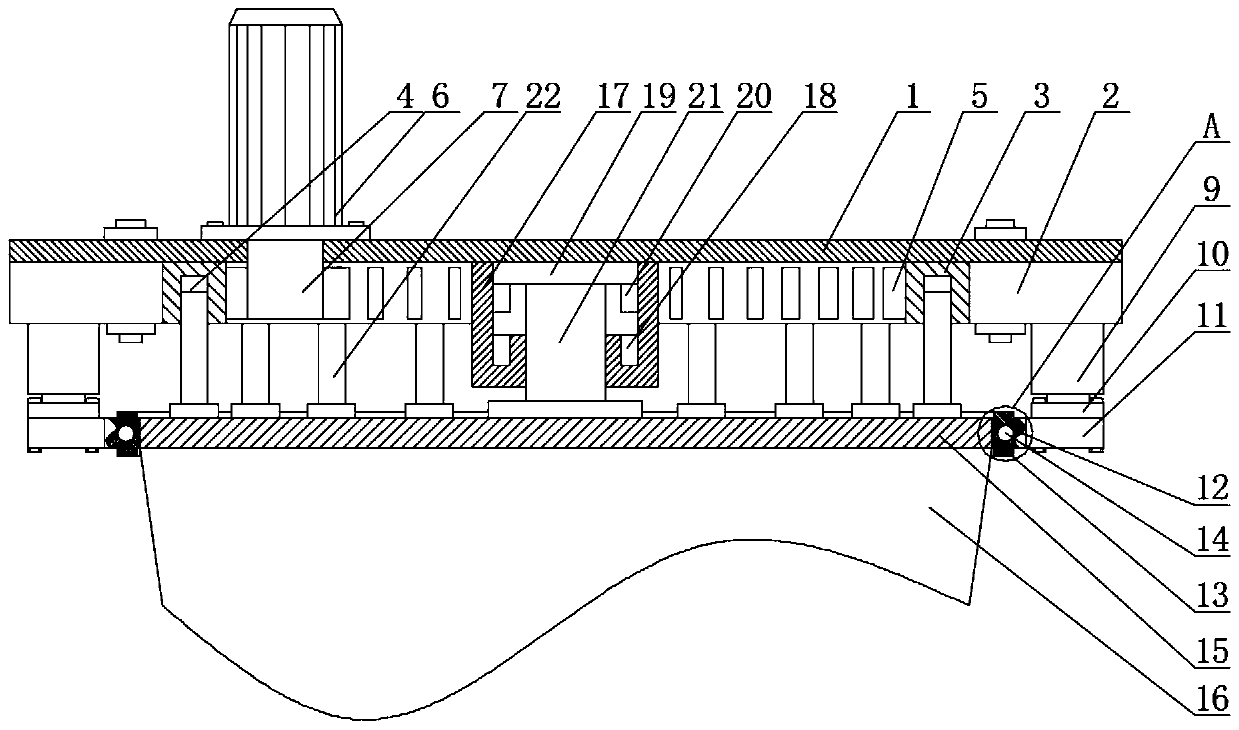
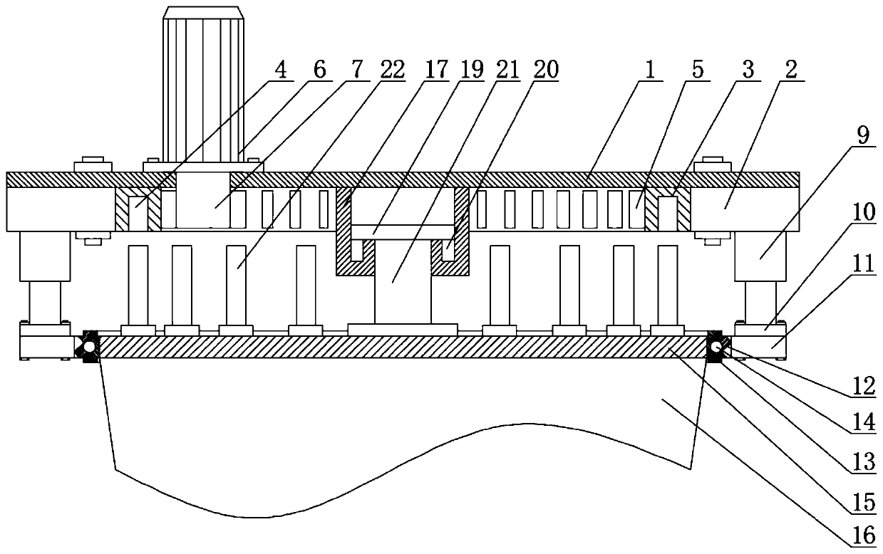
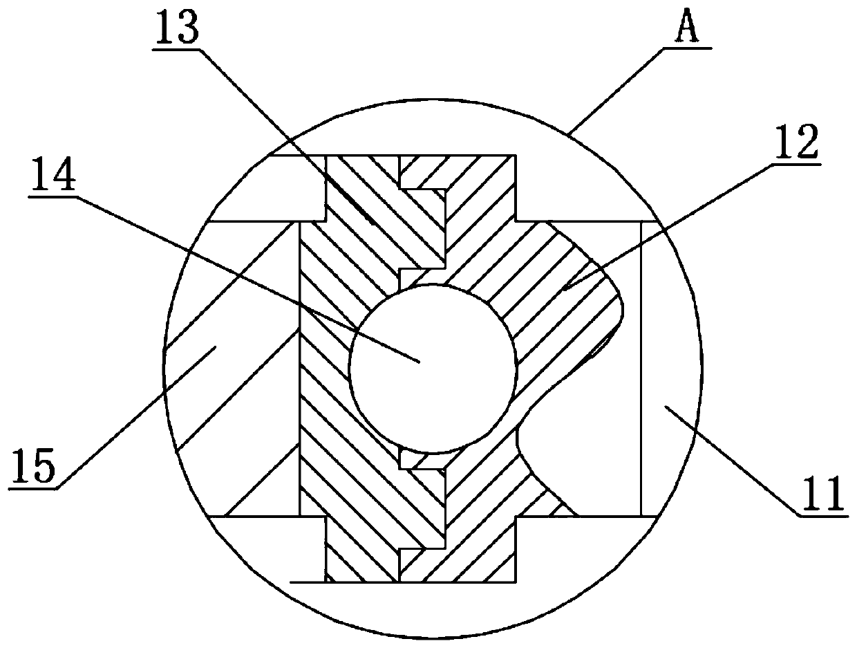
[0024] see Figure 1-7 , a wind turbine pitch device, comprising a head plate 1, the outer ring of the lower surface of the head plate 1 is fixedly installed with a fixed installation ring 2, and the inner ring of the fixed installation ring 2 is movably connected with a pitch bearing 3, and the pitch bearing 3 is provided with a card slot 4, the inner ring of the pitch bearing 3 is fixedly provided with a tooth groove 5, one end of the upper surface of the he...


PUM


Abstract

The invention relates to the technical field of wind power generation, and discloses a variable pitch device for a wind power generator. The variable pitch device comprises a nose plate; and a fixed mounting ring is fixedly mounted on an outer ring on the lower surface of the nose plate. A fixed way of a paddle is changed to a movable way; and when wind changes, the paddle is first detached from ablade bearing, then a variable pitch motor is started to drive the blade bearing to rotate, and next the paddle is pushed by a hydraulic rod to return to the original position, so that clamping rodsare inserted in clamping grooves, the angle adjustment of the paddle on the blade bearing is started, and the variable pitch motor first drives the blade bearing to rotate before the paddle rotates every time, and therefore, tooth grooves in the inner ring of the blade bearing rotate to different positions before the paddle is adjusted to enable the tooth grooves in the inner ring to be meshed with a variable pitch gear in turn, thereby ensuring the wear uniformity of the tooth grooves in the inner ring of the blade bearing, and prolonging the service life of the wind power generator.

Description

technical field [0001] The invention relates to the technical field of wind power generation, in particular to a wind power generator pitch control device. Background technique [0002] A wind generator is a new type of energy generating device that uses wind energy to do work on the blades, so that the blades drive the generating shaft of the generator to rotate to generate electric energy. The pitch device is one of the key components of the wind generator. The existing wind generator There are generally three blades, and each blade is equipped with a set of pitch-changing device. The pitch-changing device adjusts the angle of the blade according to the data obtained by the sensor when the wind force changes, so as to ensure that the generator can obtain the maximum Energy, to ensure the power generation efficiency and stability of the power generation price, but there are always some problems in the use of the existing generator pitch device: [0003] 1. The existing pit...

Claims


Application Information

Patent Timeline
IPC IPC(8): F03D7/02F03D7/04
CPCF03D7/0224F03D7/04Y02E10/72
Inventor 吴志华
Owner 吴志华
Why Eureka
Try Eureka