[0030] The embodiments of the present invention are described in detail below. Examples of the embodiments are shown in the accompanying drawings, in which the same or similar reference numerals indicate the same or similar elements or elements with the same or similar functions. The embodiments described below with reference to the accompanying drawings are exemplary, and are intended to explain the present invention, but should not be construed as limiting the present invention.
[0031] In the description of the present invention, it should be understood that the terms "center", "longitudinal", "transverse", "length", "width", "thickness", "upper", "lower", "front", " "Back", "Left", "Right", "Vertical", "Horizontal", "Top", "Bottom", "Inner", "Outer", "Clockwise", "Counterclockwise", "Axial" , "Radial", "Circumferential", etc. indicate the orientation or positional relationship based on the orientation or positional relationship shown in the drawings, and are only for the convenience of describing the present invention and simplifying the description, rather than indicating or implying the pointed device or The element must have a specific orientation, be constructed and operated in a specific orientation, and therefore cannot be understood as a limitation of the present invention.
[0032] In addition, the terms "first" and "second" are only used for descriptive purposes, and cannot be understood as indicating or implying relative importance or implicitly indicating the number of indicated technical features. Therefore, the features defined with "first" and "second" may explicitly or implicitly include at least one of the features. In the description of the present invention, "a plurality of" means at least two, such as two, three, etc., unless otherwise specifically defined.
[0033] In the present invention, unless otherwise clearly specified and limited, the terms "installed", "connected", "connected", "fixed" and other terms should be understood in a broad sense, for example, it may be a fixed connection or a detachable connection , Or integrated; it can be mechanically connected or electrically connected; it can be directly connected or indirectly connected through an intermediary, it can be the internal communication of two components or the interaction relationship between two components, unless otherwise specified The limit. For those of ordinary skill in the art, the specific meanings of the above terms in the present invention can be understood according to specific circumstances.
[0034] In the present invention, unless otherwise clearly defined and defined, the first feature "on" or "under" the second feature may be in direct contact with the first and second features, or indirectly through an intermediary. contact. Moreover, the "above", "above" and "above" of the first feature on the second feature may mean that the first feature is directly above or obliquely above the second feature, or it simply means that the level of the first feature is higher than the second feature. The "below", "below", and "below" of the second feature of the first feature may mean that the first feature is directly below or obliquely below the second feature, or it simply means that the level of the first feature is smaller than the second feature.
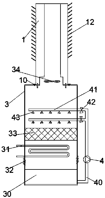
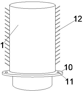
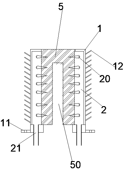
[0035] Such as Figure 1-3 As shown, the high-efficiency mist-eliminating cooling tower of this embodiment includes a cooling tower body 3, a collecting pool 30 arranged at the bottom of the cooling tower body 3, a cooling coil 31 arranged on the upper part of the collecting pool 30, and arranged in the collecting pool 30 and The first air inlet 32 between the cooling coils 31, the water spray packing layer 33 arranged on the upper part of the cooling coil 31, the water distribution pipe 41 horizontally arranged on the upper part of the water spray packing layer 33, and the water distribution pipe 41 arranged at the bottom of the water distribution pipe 41 The spray head 43 and the exhaust fan 34 arranged on the top of the cooling tower body 3, the mist eliminator 1 arranged on the exhaust fan 34, the spray pump 4 is arranged on the water distribution pipe 41, and the water distribution pipe 41 is equipped with a check Valve 42, the spray pump inlet pipe 40 of the spray pump 4 is connected with the sump 30, the water outlet of the spray pump 4 is connected with the water distribution pipe 41, the spray pump 4 is provided with a power interface and a switch, and the cover 1 is connected from A steam passage 50, a water catching chamber 5, and a condensing chamber 2 are arranged from the inside to the outside. The steam passage 50 is used to connect the cooling tower fan port. The water catching chamber 5 is filled with sponge. The lower part of the condensing chamber 2 is provided with a water collecting pipe 21 for catching A plurality of small cone-shaped thorns 20 are inserted into the water chamber 5 on the side close to the condensation chamber 2, a mounting plate 10 is provided on the cover body, mounting holes 11 are provided on the mounting plate 10, and multiple sets of heat dissipation fins 12 are provided on the outer side of the cover body. , The shape of the cover body 1 is cylindrical, the small conical thorn 20 is an all-plastic needle, and the condensation chamber 2 is annular.
[0036] The water distribution pipeline 41 in the high-efficiency mist-eliminating cooling tower in this embodiment is a double-layer.
[0037] In this embodiment, the surfaces of the first hydrophobic plate 22 and the second hydrophobic plate 23 in an efficient mist-eliminating cooling tower are coated with ZXL-CSS super-hydrophobic self-cleaning paint.
[0038] In this embodiment, the first hydrophobic plate hydrophilic protrusion 220 and the second hydrophobic plate hydrophilic protrusion 230 in an efficient mist-eliminating cooling tower are made of hydrophilic glass.
[0039] The diameter of the hydrophilic protrusions 220 of the first hydrophobic plate in the high-efficiency mist-eliminating cooling tower of this embodiment is 0.6 mm, and the distance between the hydrophilic protrusions 220 of adjacent first hydrophobic plates is 0.6 mm.
[0040] The diameter of the hydrophilic protrusions 230 of the second hydrophobic plate in the high-efficiency mist-eliminating cooling tower of this embodiment is 0.6 mm, and the distance between the hydrophilic protrusions 230 of the adjacent second hydrophobic plates is 0.6 mm.
[0041] In the description of this specification, descriptions with reference to the terms "one embodiment", "some embodiments", "examples", "specific examples", or "some examples" etc. mean specific features described in conjunction with the embodiment or example , Structure, materials or features are included in at least one embodiment or example of the present invention. In this specification, the schematic representations of the above-mentioned terms do not necessarily refer to the same embodiment or example. Moreover, the described specific features, structures, materials or characteristics can be combined in any one or more embodiments or examples in a suitable manner. In addition, those skilled in the art can combine and combine the different embodiments or examples and the characteristics of the different embodiments or examples described in this specification without contradicting each other.
[0042] Although the embodiments of the present invention have been shown and described above, it can be understood that the above embodiments are exemplary and should not be construed as limiting the present invention. A person of ordinary skill in the art can comment on the above-mentioned embodiments within the scope of the present invention. Changes, modifications, replacements and modifications of the embodiments should all be included in the protection scope of the present invention.