Counter flow type heat exchanger provided with flat tubes

A heat exchanger, counter-flow technology, applied in the field of flat-tube counter-flow heat exchangers, can solve the problems of uneven distribution of liquid fluid in the evaporator, excessive consumption of circulating pump power, and short heat transfer process of fins, etc. The synergistic effect is obvious, the effect of eliminating the inlet section effect and increasing the average temperature difference of heat transfer

Active Publication Date: 2014-03-19
HUNAN JINSONG MACHINERY
View PDF9 Cites 6 Cited by
  • Summary
  • Abstract
  • Description
  • Claims
  • Application Information

AI Technical Summary

Problems solved by technology

[0021] However, the current microchannel heat exchanger technology also has the following disadvantages: ①It is easy to build a water bridge on the fins and block the air duct; ②As an evaporator, the liquid fluid distribution is not uniform enough, which affects the heat exchange effect; ③The design is not flexible enough, which affects the actual application effect, it is difficult to use it as an evaporator; ④The flow of the microchannel is too long, which not only increases the fluid resistance and consumes too much circulation pump power, but also the eff...

Method used


Image

  • Counter flow type heat exchanger provided with flat tubes
  • Counter flow type heat exchanger provided with flat tubes
  • Counter flow type heat exchanger provided with flat tubes

Examples


Embodiment 1

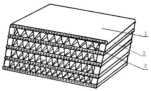
[0041] refer to figure 1 , this embodiment includes flat tubes 1 and fins 2, the two sides of the fins 2 are equipped with sealing strips 3, the flat tubes 1 and the fins 2 are alternately arranged in parallel, and the flow path direction of the flat tubes 1 Parallel to the flow channel direction of the fins 2 on the outside of the flat tube to form a counter-current heat exchange.

[0042] In this embodiment, the heat exchange capacity on both sides can be better balanced, and the length of each small channel of the flat tube is consistent, and the resistance is equal, so that the coordination of the flow velocity field and the temperature gradient field is very ideal.

Embodiment 2

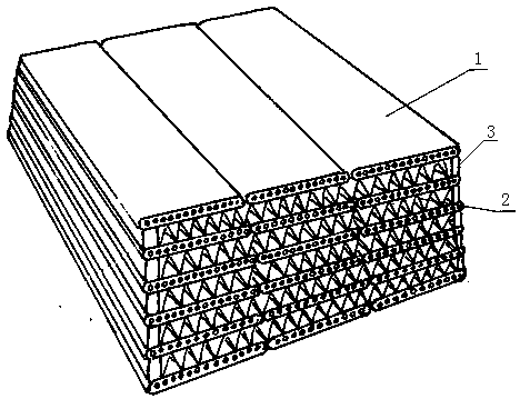
[0044] refer to figure 2 , this embodiment includes flat tubes 1 and fins 2, the two sides of the fins 2 are equipped with sealing strips 3, and on the same plane, there are three flat tubes 1, which are connected to each other to form wide flat tubes, so The wide flat tubes and the fins 2 are alternately arranged in parallel, and the flow channel direction of the wide flat tubes is parallel to the flow channel direction of the fins, forming countercurrent heat exchange.

[0045] Of course, the number of flat tubes 1 can also be other numbers, and they are connected to each other to form different wide flat tubes, which will not be repeated here. Utilizing this embodiment, the limitation of the manufacturing process due to the width of the flat tube can be overcome, and the purpose of large-scale heat exchange can be achieved.

Embodiment 3

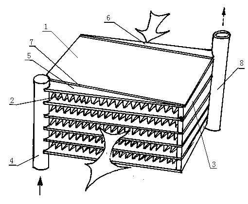
[0047] refer to image 3 , this embodiment includes flat tubes 1, fins 2, and headers. Sealing strips 3 are installed on both sides of the fins 2. The flat tubes 1 and fins 2 are alternately arranged in parallel. The flat tubes 1 The direction of the flow channel is parallel to the direction of the flow channel of the fin 2 outside the flat tube, forming a counter-current heat exchange; The header includes a confluence header 8 and a diversion header 4, and the diversion header 4 and the confluence header 8 are arranged on the opposite corners of the heat exchanger, forming a fluid channel direction in which the bottom goes in and the top goes out. The tubes 4 are connected to the flat tubes 5 of each layer, and the flat tubes 5 of each layer are connected to the flat tubes 1 of the corresponding layer through the flat tube connecting device 7, and the confluence header 8 is connected to the flat tubes 6 of each layer, and the confluence The flat tubes 6 are connected with th...


PUM


Abstract

A counter flow type heat exchanger provided with flat tubes comprises the flat tubes and fins, wherein sealing strips are mounted on two sides of each fin; the flat tubes and the fins are arranged alternatively in parallel; and the flowing directions of the flat tubes are parallel to the flowing directions of the fins outside the flat tubes, so that counter flow heating exchange is formed. The counter flow type heat exchanger provided with the flat tubes is compact in structure, small in occupied space, high in pressure resistance grade and wide in application range and can be used for an evaporator and a condenser taking carbon dioxide as a refrigerant, particularly large-scale heat exchange capability can be formed, the counter flow type heat exchanger is applicable to an evaporator and a condenser of a central air conditioner, the efficient evaporator and condenser allowing the refrigerant to pass through micro channels and water to flow from the outside of the micro channels are obtained, and energy is saved.

Description

technical field [0001] The invention relates to a flat tube counter-flow heat exchanger. Background technique [0002] In the 21st century, energy and environmental protection issues have become more and more prominent, and have become the bottleneck of my country's economic development, especially the frequent occurrence of smog in many large and medium-sized cities in my country, which not only causes harm to the health of ordinary people, but also restricts the development of my country's economy. Development and growth, such as prolonged smog weather will affect the photosynthesis of crops, resulting in reduced production of agricultural products, has become a major issue of the national economy and people's livelihood. The key to energy conservation and emission reduction is to carry out technological transformation on large emitters and ranks, such as thermal power plants, building material production enterprises, smelting, automobile exhaust, air conditioning and heati...

Claims


Application Information

Patent Timeline
IPC IPC(8): F28D9/00F28F3/02
Inventor 刘小江
Owner HUNAN JINSONG MACHINERY
Why Eureka
Try Eureka