Power electronic transformer based on virtual grid flux orientation

A technology of power electronics and virtual flux linkage, applied in the field of power systems, can solve the problems that traditional transformers cannot meet the requirements of power grid transformation and users, cannot realize automatic operation of transformers, and cannot change the power factor of power grids, etc., so as to reduce the size of equipment and cost, saving voltage sensor, and reducing the number of switching tubes

Inactive Publication Date: 2015-12-09
XIAMEN UNIV OF TECH
View PDF9 Cites 7 Cited by
  • Summary
  • Abstract
  • Description
  • Claims
  • Application Information

AI Technical Summary

Problems solved by technology

[0003] As users have higher and higher requirements for power grids and the country's plan to build smart grids, traditional transformers can no longer meet the requirements of power grid transformation and users.
It can only change the size of the grid voltage, and the electric energy can only flow from the grid to the user in a single phase, and cannot realize the two-way flow of electric energy
Today, with more and more new energy power generation, the excess power of users cannot be merged into the grid from users, which obviously cannot meet people's needs.
On the other hand, depending on the nature of users, different power factors are required, while traditional transformers cannot change the power factor of the grid and cannot meet user needs
[0004] With the development of communication technology and automation control technology, more and more attention has been paid to the automation and remote monitoring of power grid operation. The output of traditional transformers is all analog signals, and there is no controller, so it is impossible to realize the automatic operation of transformers. Monitoring is also difficult. Most of them still rely on manual meter reading or electronic sensors to monitor transformers, and then the data is online to complete the monitoring. The real-time performance is poor.

Method used


Image

  • Power electronic transformer based on virtual grid flux orientation
  • Power electronic transformer based on virtual grid flux orientation
  • Power electronic transformer based on virtual grid flux orientation

Examples


Embodiment Construction

[0032] To further illustrate the various embodiments, the present invention is provided with accompanying drawings. These drawings are a part of the disclosure of the present invention, which are mainly used to illustrate the embodiments, and can be combined with related descriptions in the specification to explain the operating principles of the embodiments. With reference to these contents, those skilled in the art should understand other possible implementations and advantages of the present invention. Components in the figures are not drawn to scale, and similar component symbols are generally used to denote similar components.

[0033] The present invention will be further described in conjunction with the accompanying drawings and specific embodiments.

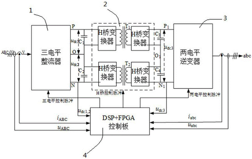
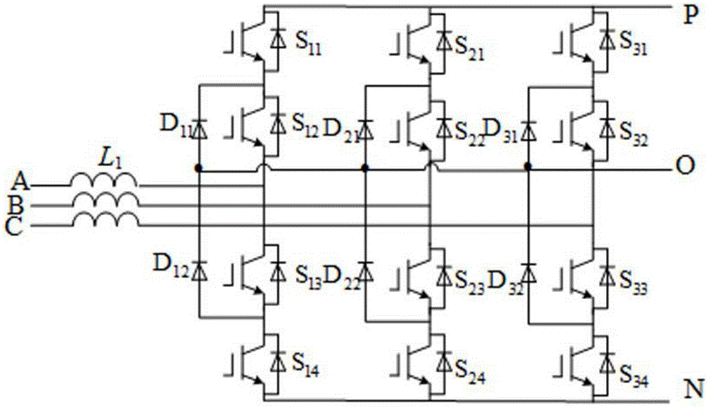
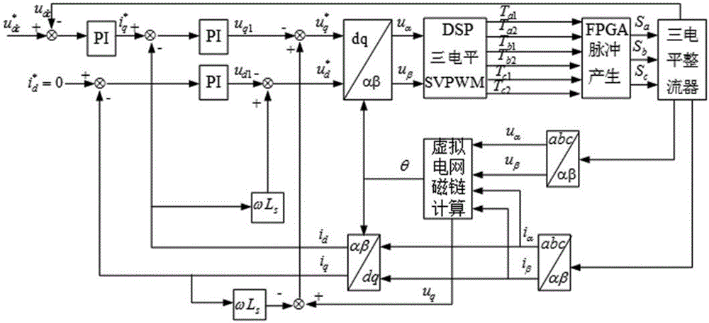
[0034] refer to figure 1 As shown, a power electronic transformer based on grid virtual flux linkage orientation in a preferred embodiment of the present invention includes a three-level rectifier 1 , an intermediate i...


PUM


Abstract

The invention relates to the technical field of power systems, and specifically relates to a power electronic transformer based on virtual grid flux orientation. The invention discloses a power electronic transformer based on virtual grid flux orientation, comprising a rectifier, a middle isolation level, an inverter, and a control board. The alternating-current side of the rectifier is connected with a grid, and the direct-current side of the rectifier is connected with a high-voltage port of the middle isolation level. The direct-current side of the inverter is connected with a low-voltage port of the middle isolation level, and the alternating-current side of the inverter is connected with a transmission line or load. The control board is connected with the rectifier, the middle isolation level and the inverter. The control board generates pulse signals, and controls on-off of power switching devices of the rectifier, the middle isolation level and the inverter. The control board adopts a directional control strategy based on virtual flux to reduce the impact of grid fluctuation on the system.

Description

technical field [0001] The invention relates to the technical field of power systems, in particular to a power electronic transformer based on grid virtual flux linkage orientation. Background technique [0002] The transformer is one of the most important and expensive components in the grid power supply and distribution system. Its main functions are to complete voltage conversion, system isolation, and noise decoupling. The main reason why traditional transformers are expensive is their large size and expensive materials. As the price of silicon steel sheets, copper and transformer oil is getting higher and higher, the manufacturing and operating costs of transformers are also getting higher and higher. Due to the large volume of traditional transformers, their use in certain occasions is also subject to certain restrictions. For example, in underground coal mines, the space is narrow, especially explosion-proof devices are required, and general transformers cannot meet...

Claims


Application Information

Patent Timeline
Patent Type & Authority Applications(China)
IPC IPC(8): H02J3/38H02M5/458
Inventor 张辑王丽霞陈天翔彭彦卿徐敏
Owner XIAMEN UNIV OF TECH
Why Eureka
Try Eureka