
Integrated unsealed tank for waste heat recovery of industrial wastewater

A waste heat recovery and industrial waste water technology, applied in the direction of heat exchangers, indirect heat exchangers, cleaning heat transfer devices, etc., can solve the problem of affecting the heat exchange efficiency of the water exchange pipe, occupying the normal production time of the tank, and the sediment is not easy to implement Cleaning and other problems, to achieve the effect of convenient cleaning operation, avoiding the normal production and running time of the tank body, and the linkage structure design is ingenious and reasonable

Active Publication Date: 2020-06-09
WENZHOU TAICHANG TOWER MFG
View PDF11 Cites 0 Cited by
  • Summary
  • Abstract
  • Description
  • Claims
  • Application Information

AI Technical Summary

Problems solved by technology

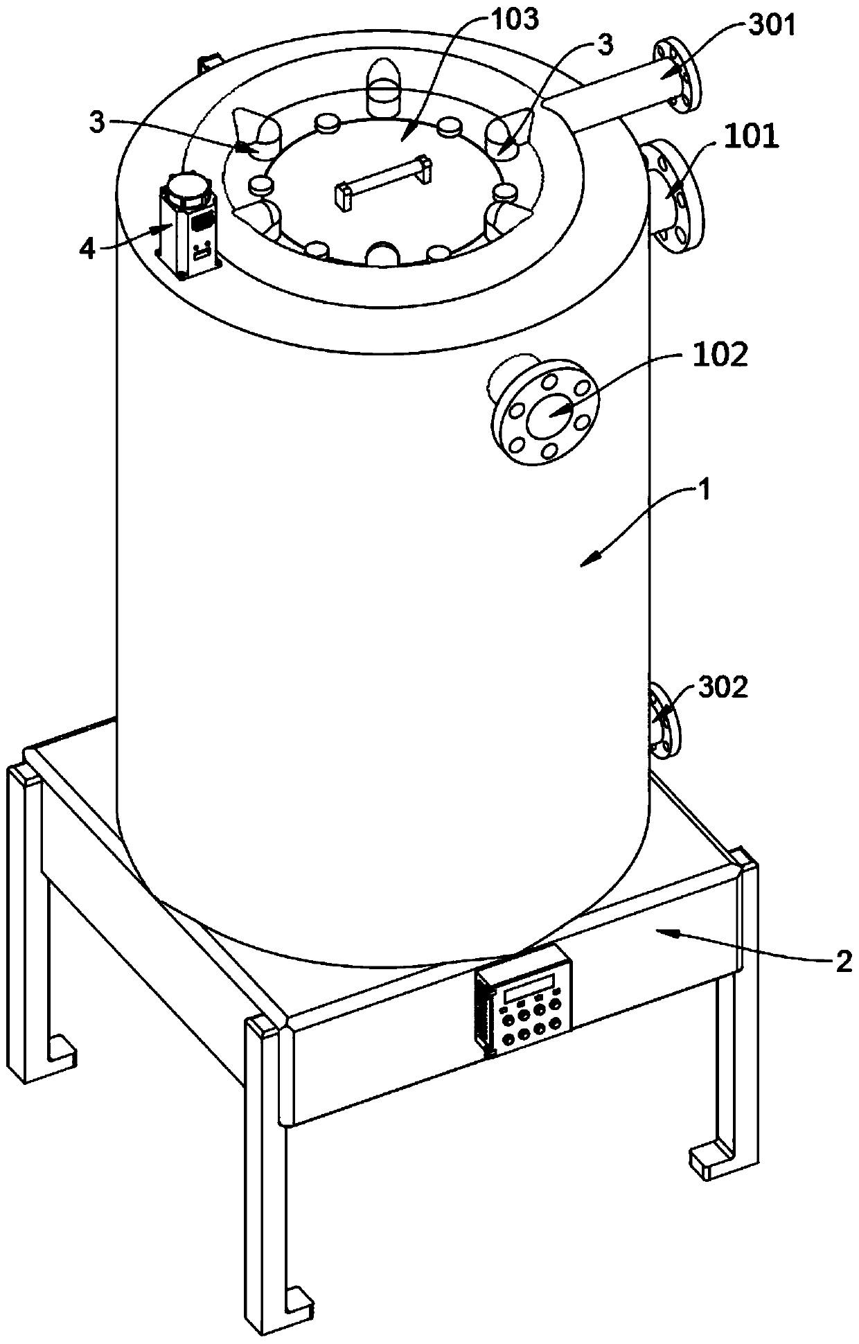
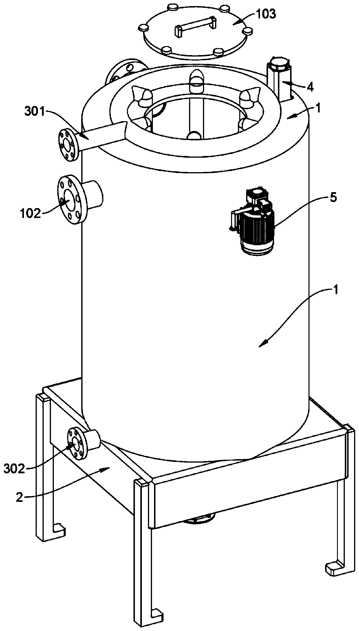
[0005] The purpose of the present invention is to provide an integrated unsealed tank body for waste heat recovery from industrial waste water, so as to solve the problem that the deposited impurities on the surface of the internal water exchange pipes proposed in the above background technology will affect the heat exchange efficiency of the water exchange pipes. Moreover, the sediment on the surface of the heat exchange pipe is not easy to clean, and it is necessary to manually enter the tank for cleaning. The operation is extremely troublesome, and the tank needs to be shut down when cleaning the settled sludge at the bottom of the tank, which takes up the normal production time of the tank , which affects the production efficiency

Method used


Image

  • Integrated unsealed tank for waste heat recovery of industrial wastewater
  • Integrated unsealed tank for waste heat recovery of industrial wastewater
  • Integrated unsealed tank for waste heat recovery of industrial wastewater

Examples


Embodiment Construction

[0035] The following will clearly and completely describe the technical solutions in the embodiments of the present invention with reference to the accompanying drawings in the embodiments of the present invention. Obviously, the described embodiments are only some, not all, embodiments of the present invention.

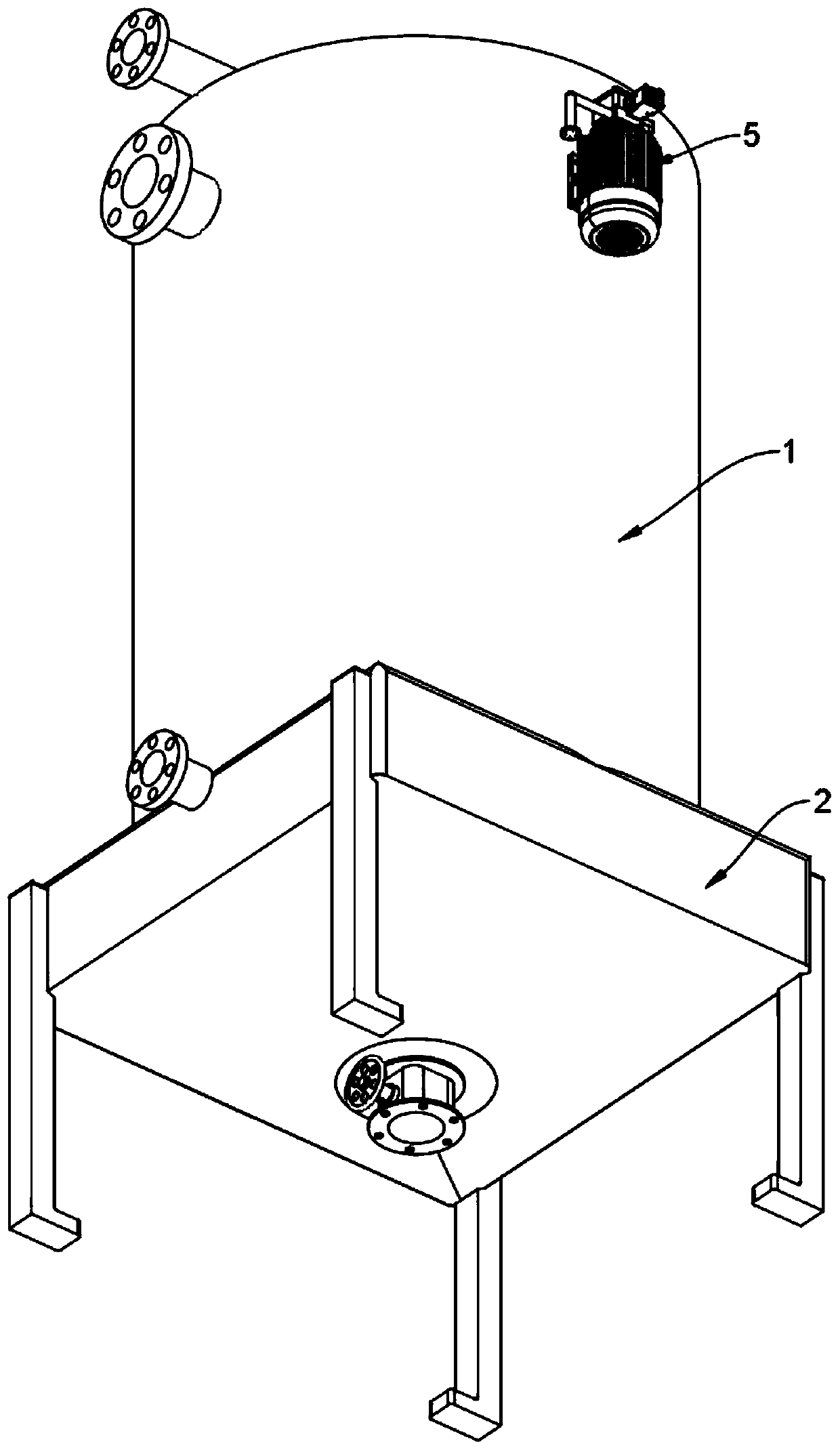
[0036] see Figure 1 to Figure 14 , an embodiment provided by the present invention: an integrated unsealed tank body for waste heat recovery of industrial waste water, comprising a tank body 1, a water spray disc 6 and a supporting brush rod 7, and the tank body 1 includes a waste water inlet pipe 101, the waste water overflow pipe 102 and the tank cover 103, a waste water inlet pipe 101 and a waste water overflow pipe 102 are connected with a waste water inlet pipe 101 and a waste water overflow pipe 102 on the circumferential outer wall of the top position of the tank body 1 at an included angle of 90°, and a waste water overflow pipe 102 is connected. A circular op...


PUM


Abstract

The invention discloses an integrated unsealed tank for waste heat recovery of industrial wastewater, and relates to the technical field of waste heat recovery tanks. The problem that in an existing tank, the tank needs to be stopped when settling sludge at the bottom of the tank body is cleaned, the normal production time of the tank body is occupied, and the production efficiency is affected issolved. The integrated unsealed tank body for waste heat recovery of industrial wastewater comprises a tank body, a water spraying disc and a supporting brush rod, wherein a wastewater inlet pipe anda wastewater overflow pipe are welded with an inclined angle of 90 degrees on the circumferential outer wall of the top end position of the tank body in an up-down interval and communicated mode; anda circular opening is formed in the center of the top end wall plate of the tank body in a penetrating manner; and a tank cover is inserted into the circular opening. The back-flushing kinetic energyof water can be used as a driving power source for cleaning the wall of a heat exchange tube; and compared with a transmission mode by adopting a mechanical rotating shaft mechanism, the structure issimple, the failure rate is low, the production cost and the manufacturing difficulty are both effectively reduced, and the integrated unsealed tank has relatively high practicability and is easy to popularize.

Description

technical field [0001] The invention relates to the technical field of waste heat recovery tanks, in particular to an integrated unsealed tank body for recovery of waste heat from industrial waste water. Background technique [0002] A large amount of industrial wastewater is produced in the production process of many industries. Apart from containing a large amount of industrial pollutants, most of these wastewaters have a common characteristic-high temperature, and the discharge of high-temperature industrial wastewater into the environment will cause great harm to animals and plants. Moreover, high-temperature industrial wastewater contains a large amount of heat. If it is directly discharged into the environment, it will cause energy waste. This requires the use of a tank for industrial wastewater waste heat recovery. [0003] For example, the patent No. CN201320112857.3 discloses a waste heat recovery tank for waste water, which includes a tank body and a filter screen....

Claims


Application Information

Patent Timeline
IPC IPC(8): F28D7/16F28G1/00
CPCF28D7/16F28G1/00
Inventor 刘贤方
Owner WENZHOU TAICHANG TOWER MFG
Learn More