Multi-degree-of-freedom sample rod

A technology of sample rods and degrees of freedom, applied in the field of sample rods, can solve the problems of easy deformation of flexible claws, complex relationships, and inability to observe, and achieve the effect of reducing design and manufacturing requirements

Active Publication Date: 2020-06-09
ZHEJIANG UNIV
View PDF5 Cites 2 Cited by
  • Summary
  • Abstract
  • Description
  • Claims
  • Application Information

AI Technical Summary

Problems solved by technology

[0005] The disadvantages of this three-dimensional probe are: 1. The flexible claw is easy to deform. In order to maintain the friction between it and the ball, the shape of the flexible claw needs to be adjusted frequently, but there are many flexible claws, and it is impossible to ensure that each The consistency of the flexible wire claws, resulting in the lower and lower reliability and accuracy of the three-dimensional probe with the time and frequency of use
2. The length of the flexible wire claw makes there is a gap between the sample holder and the ball. When the ball circulates, the sample holder will move away from the ball or close to the ball along the wire claw, so as to realize the axial displacement of the sample. , but the sample holder is suspended on the ball through flexible wire claws, the sample holder and the sample on it will fall down due to gravity, and the position accuracy is not high
The observation field of view in the transmission electron microscope is at the nanometer and micron level, and the position deviation of the sample due to gravity is likely to cause the area to be observed on the sample to deviate from the observation field of view of the electron microscope and cannot be observed; and the existence of position deviation makes it difficult to place the sample Adjust the area to be observed to a suitable position and angle for observation
3. When the probe clamping device moves back and forth along the axial direction of the piezoelectric ceramic tube, the relationship between the shape of the flexible wire claw and the above-mentioned frictional force is complicated, and it is difficult to ensure that the frictional force is always suitable by adjusting its shape
In addition, the probe clamping device is affected by gravity, which makes it easy to generate coupling motion during rough adjustment, and it is difficult to accurately control the probe; even due to improper adjustment of the shape of the flexible wire claw, the small ball cannot be grasped, which may cause the probe to clamp The device falls into the device, causing damage to the device

Method used


Image

  • Multi-degree-of-freedom sample rod
  • Multi-degree-of-freedom sample rod
  • Multi-degree-of-freedom sample rod

Examples


Embodiment Construction

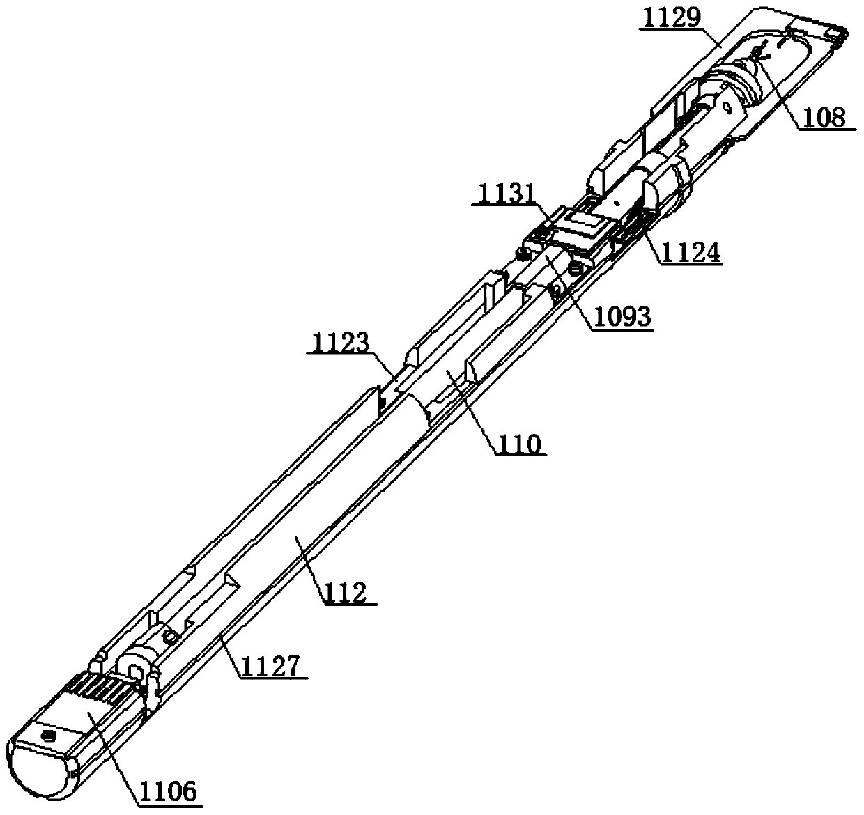
[0166] figure 1 is a multi-degree-of-freedom sample holder. Such as figure 2 As shown, a nanopositioner is provided on the sample rod, and the nanopositioner includes a driving part 101, a joint ball 103 and a pressing part assembly, the joint ball 103 is fixed with the driving part 101, and the pressing part assembly includes at least two pressing parts 105 and an elastic connection Component 104 , the elastic connection component 104 connects adjacent pressure pieces, the pressure piece component embraces the joint ball 103 , and there is a pre-tightening force between the pressure piece and the joint ball 103 . For example, a piezoelectric ceramic tube is used as the drive element 101 .

[0167] Pressed piece

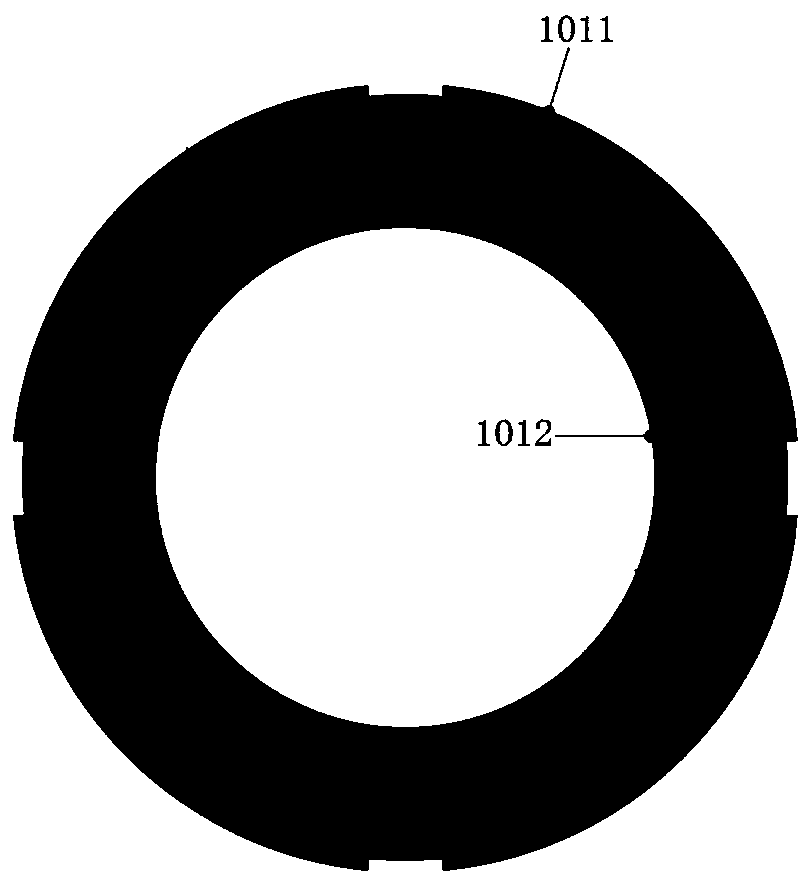
[0168] In some embodiments, such as figure 2 As shown, each pressing piece has a concave part 1051 and a connecting part 1052 respectively, and the elastic connection assembly 104 is arranged between the connecting parts 1052 of adjacent pressing pieces, and th...


PUM


Abstract

The invention discloses a multi-degree-of-freedom sample rod. The sample rod comprises a framework and a rotating shaft, wherein a magnet is arranged at a tail end of the rotating shaft, the frameworkis provided with a leading-out circuit board, the framework is provided with a notch, the leading-out circuit board comprises a bent part, the bent part is located in the notch, and a magnetic fieldsensor is fixed to the bent part. The sample rod is advantaged in that the position information of the rotating shaft can be detected, when the rotating shaft rotates and moves back and forth, the magnetic field changes accordingly, the magnetic field sensor measures the magnetic field, the position information of the rotating shaft can be obtained through solving, the magnetic field sensor can befixed through soldering tin connection between the magnetic field sensor and the leading-out circuit board, short circuit of one pair of pins on the leading-out circuit board can be conducted, and the number of wires needing to be connected is reduced; the leading-out circuit board comprises a plane part and a bending part, the plane part and the bending part are vertically laid on a surface of the framework, the magnetic field sensor is fixed to the bending part, and the bending circuit board is small in occupied area and easy to disassemble.

Description

technical field [0001] The invention relates to a sample rod used under an electron microscope and a transmission electron microscope. Background technique [0002] Transmission electron microscopy (TEM) can see fine structures smaller than 0.2 μm that cannot be seen clearly under ordinary optical microscopes. These structures are called submicrostructures or ultrastructures. In 1932, Ruska invented the transmission electron microscope with electron beam as the light source. Currently, the resolution of TEM can reach 0.2nm. [0003] In situ observation techniques have a long history in transmission electron microscopy research. By applying various physical effects on the sample and using a transmission electron microscope (TEM) to observe the changes in the microstructure and chemical state of the material, it is possible to intuitively study the performance of the material or device in the actual use process. For the performance of the material The research has important ...

Claims


Application Information

Patent Timeline
Patent Type & Authority Applications(China)
IPC IPC(8): G01N23/02
CPCG01N23/02G01N2223/03G01N2223/102G01N2223/309
Inventor 王宏涛张奕志
Owner ZHEJIANG UNIV
Why Eureka
Try Eureka